Optical amplifier pre-emphasis and equalization method and optical communications system incorporating same

a technology of optical amplifiers and equalization methods, applied in the field of optical amplifier pre-emphasis and equalization methods and optical communications systems incorporating the same, can solve the problems of reducing the performance of bit error rate (ber) for some communications channels, introducing losses to offset gain peaks, and reducing the signal-to-noise ratio (snr) flat, efficient and cost-effectively alleviating the optical amplifier gain ripple penalty

Active Publication Date: 2008-05-06
CIENA
View PDF10 Cites 11 Cited by
  • Summary
  • Abstract
  • Description
  • Claims
  • Application Information

AI Technical Summary

Benefits of technology

[0006]In various exemplary embodiments, the present invention provides an optical amplifier pre-emphasis and equalization method that efficiently and cost-effectively alleviates the optical amplifier gain ripple penalty experienced in conventional optical communications systems. This optical amplifier pre-emphasis and equalization method includes storing measured communications channel signal gain ripple information, acquired during factory calibration, in the internal memory of each optical amplifier module. When the optical amplifiers are assembled into a chain, system software retrieves this communications channel signal gain ripple information from each optical amplifier module and computes the pre-emphasis or equalization required for each channel in order to obtain a flat signal-to-noise ratio (SNR) at a receiver. The optical amplifier pre-emphasis and equalization method also includes measuring the ambient temperature of each optical amplifier module and applying a correction based on the expected change in gain response of each optical amplifier. The optical amplifier pre-emphasis and equalization method further includes, for Raman amplifiers and the like, applying a fiber type, gain setting, GFF error, etc. correction based on the expected change in gain response of each optical amplifier. The optical amplifier pre-emphasis and equalization method relies on using VOAs at the sources and / or DGEs / reconfigurable blocking filters (RBFs) that are already deployed at optical add / drop multiplexer (OADM) nodes in the optical signal path to pre-emphasize or equalize the optical channels. In other words, the gain ripple is corrected by pre-emphasizing the input spectrum of the in-line amplifier (ILA) chain, or equalizing points in between, thereby improving the SNR of weak channels and reducing non-linearity on the “hot” channels.

Problems solved by technology

This results in degraded bit error rate (BER) performance for some communications channels.
The gain ripple penalty stems from the optical amplifiers and, to a lesser extent, from dispersion compensating modules (DCMs), the fiber plant, etc., and it is usually a reach-limiting constraint for an optical communications system.
The DGE has a loss spectrum that tracks the gain spectrum of the optical amplifiers, thereby introducing losses to offset gain peaks.
The drawback to these approaches is that OPM and DGE elements are relatively expensive, especially when used in low channel count optical communications systems.

Method used


Image

  • Optical amplifier pre-emphasis and equalization method and optical communications system incorporating same
  • Optical amplifier pre-emphasis and equalization method and optical communications system incorporating same
  • Optical amplifier pre-emphasis and equalization method and optical communications system incorporating same

Examples


Embodiment Construction

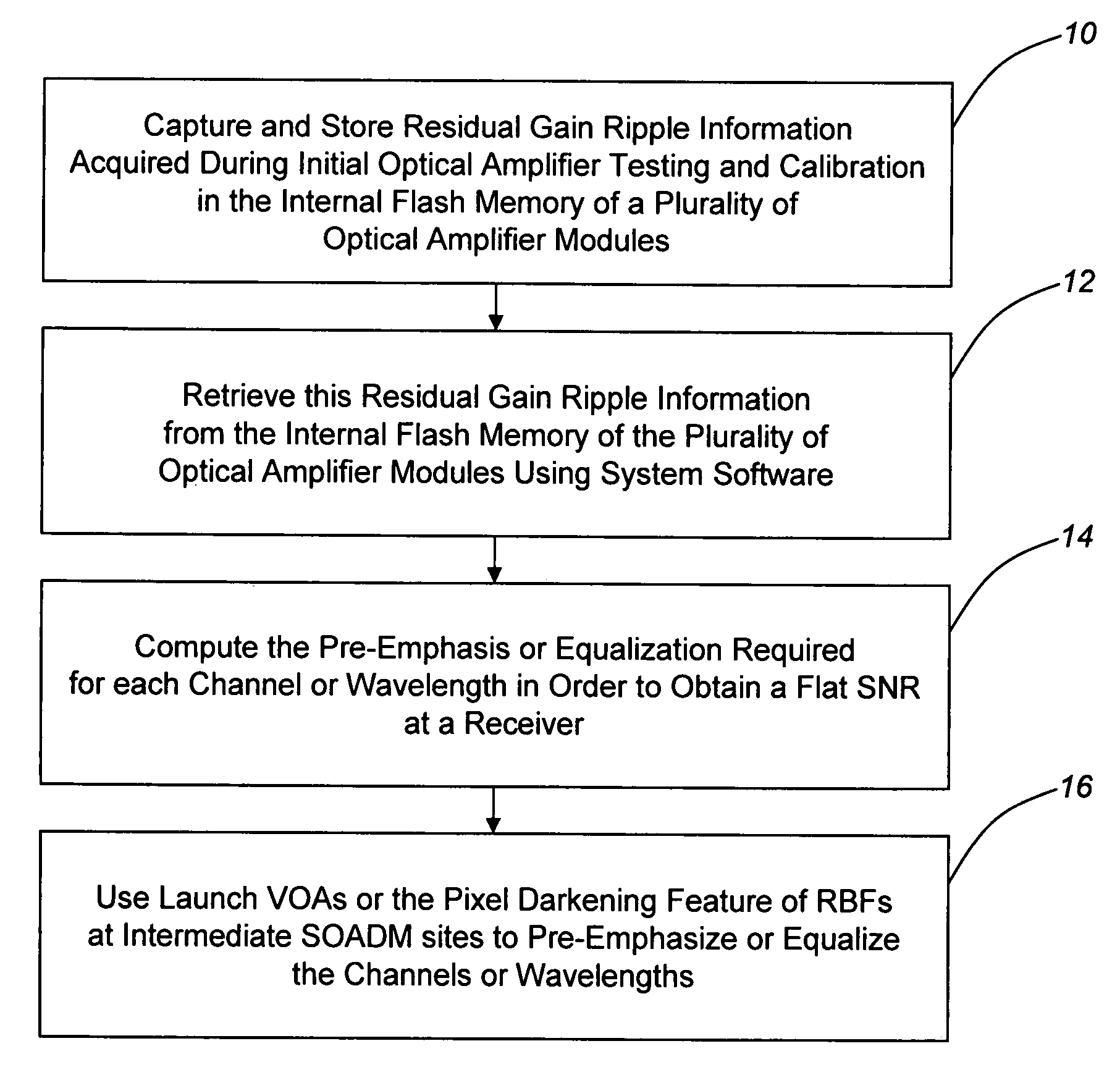
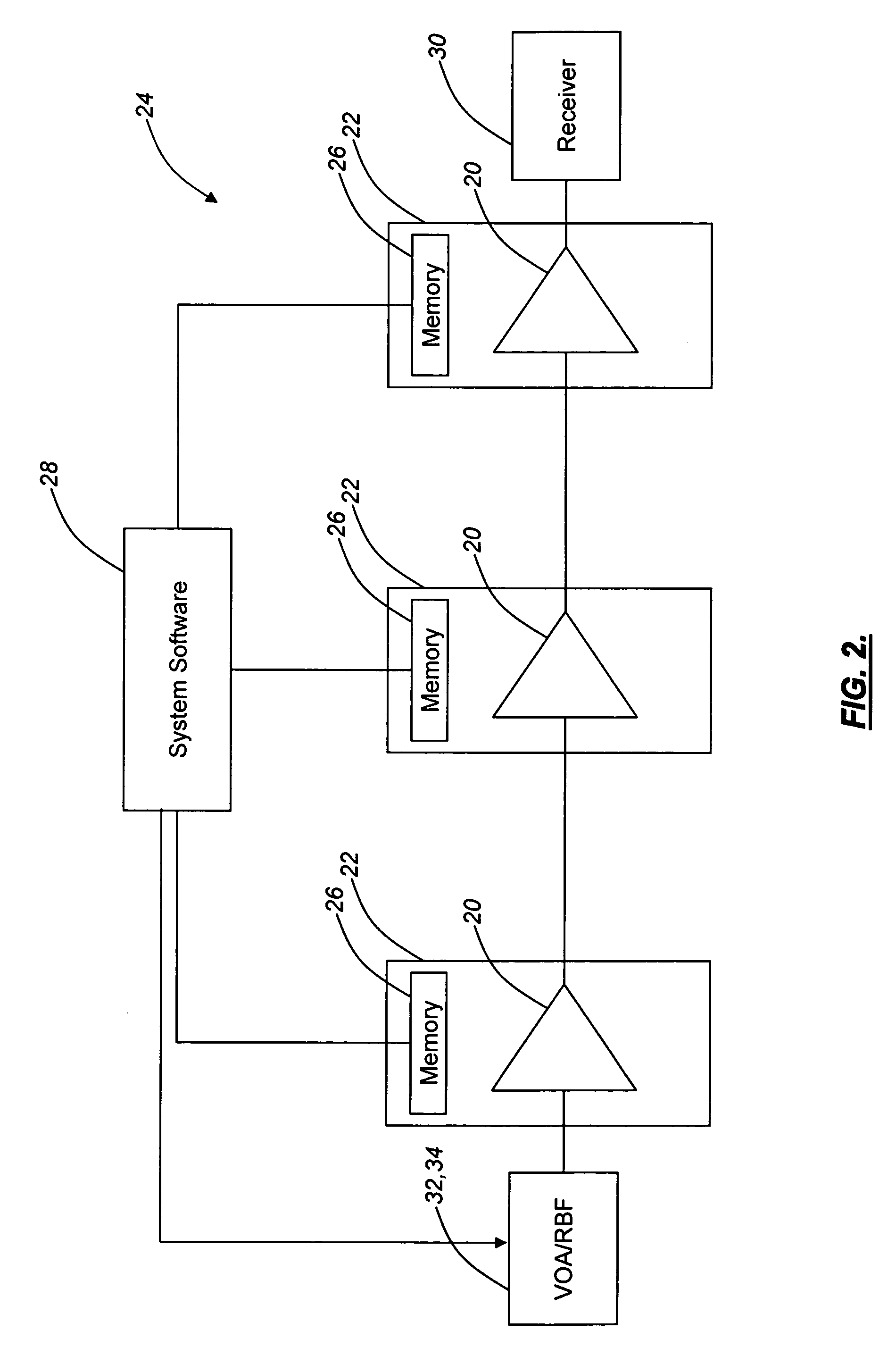
[0021]As described above, conventional approaches for alleviating the optical amplifier gain ripple penalty involve the use of a gain equalization filter or the like. The gain equalization filter has a loss spectrum that tracks the gain spectrum of an optical amplifier, thereby introducing losses to offset gain peaks. Conventional approaches for alleviating the optical amplifier gain ripple penalty also involve the use of an OPM or the like for the active measurement of communications channel signal gain ripple at a receiver or an intermediate point in the optical amplifier chain and a feedback mechanism to provide this communications channel signal gain ripple information to a controlling element, such as a VOA, DGE, or the like. The drawback to these approaches is that OPM and DGE elements are relatively expensive, especially when used in low channel count optical communications systems.

[0022]In various exemplary embodiments, the present invention provides an optical amplifier pre...


PUM


Abstract

The present invention provides an optical amplifier pre-emphasis and equalization method that alleviates the optical amplifier gain ripple penalty experienced in conventional optical communications systems. This method includes storing measured communications channel signal gain ripple information, acquired during factory calibration, in the internal memory of each optical amplifier module. When the optical amplifiers are assembled into a chain, system software retrieves this communications channel signal gain ripple information from each optical amplifier module and computes the pre-emphasis or equalization required for each channel in order to obtain a flat SNR at a receiver. The method also includes measuring the ambient temperature of each optical amplifier module and applying a correction based on the expected change in gain response of each optical amplifier. The method further includes, for Raman amplifiers and the like, applying a fiber type, gain setting, GFF error, etc. correction based on the expected change in gain response of each optical amplifier. The method relies on using VOAs at the sources or DGEs / RBFs in the optical signal path to pre-emphasize or equalize the optical channels.

Description

FIELD OF THE INVENTION[0001]The present invention relates generally to the telecommunications and optical networking fields. More specifically, the present invention relates to an optical amplifier pre-emphasis and equalization method and an optical communications system incorporating the same. Advantageously, the optical amplifier pre-emphasis and equalization method of the present invention efficiently and cost-effectively alleviates the optical amplifier gain ripple penalty experienced in conventional optical communications systems.BACKGROUND OF THE INVENTION[0002]In optical communications systems that use wavelength division multiplexing (WDM), multiple wavelengths of light are used to support multiple communications channels on a single fiber. Optical amplifiers, such as erbium-doped fiber amplifiers (EDFAs), Raman amplifiers, and the like, are used in these optical communications systems to amplify optical signals that experience attenuation over multi-kilometer fiber optic li...

Claims


Application Information

Patent Timeline
Patent Type & Authority Patents(United States)
IPC IPC(8): H01S4/00H04B10/12
CPCH04B10/0797H04B10/2935H01S3/06758H01S2301/02
Inventor SRIDHAR, BALAKRISHNANFRANKEL, MICHAEL Y.
Owner CIENA
Why Eureka
Try Eureka