
Electrophotographic photoreceptor, method for manufacturing the electrophotographic photoreceptor, and image forming apparatus and process cartridge using the electrophotographic photoreceptor

a photoreceptor and electrophotography technology, applied in the field of electrophotographic photoreceptors, can solve the problems of mechanical ablation of the uppermost layer of the photoreceptor, inability to use the photoreceptor with a smaller diameter but a shorter life, and inability to produce images. stably, increase the residual potential

Active Publication Date: 2008-05-13
RICOH KK
View PDF37 Cites 8 Cited by
  • Summary
  • Abstract
  • Description
  • Claims
  • Application Information

AI Technical Summary

Benefits of technology

[0038]Accordingly, an object of the present invention is to provide a photoreceptor which can stably produce images for a long period of time without causing problems such as the background development problem (i.e., increase of residual potential), and the dielectric breakdown problem.
[0039]Another object of the present invention is to provide an image forming apparatus and a process cartridge which can produced high quality images for a long period of time without causing the problems mentioned above and without frequently changing the photoreceptor.

Problems solved by technology

However, a photoreceptor which has a smaller diameter but has a shorter life cannot be used, and it is a problem to be solved how to develop a photoreceptor having a small diameter and a long life.
The former problem (electrostatic fatigue) is that when a photoreceptor is repeatedly subjected to image forming operations such as charging and light irradiating, the electric potentials (potentials of lighted portions and non-lighted portions) formed on the photoreceptor change.
The latter problem is that the uppermost layer of a photoreceptor is mechanically abraded after repeated use by members contacting the photoreceptor such as cleaners.
If the uppermost layer is thinned due to the abrasion, the strength of electric field formed on the photosensitive layer increases, resulting in acceleration of the electrostatic fatigue, and thereby the life of the photoreceptor is further shortened.
In addition, when the surface of the photoreceptor is scratched by the contacting members, undesired images (such as streak images) are formed, resulting in shortening of the life of the photoreceptor.
In such full color image forming apparatus, production of abnormal images is typically caused by the photoreceptor used.
First, abnormal images are caused by scratches formed on the surface of the photoreceptor.
Secondly, abnormal images are formed when the photoreceptor has electrostatic fatigue.
In the second case, abnormal images (typically, background development) are caused by deterioration of the photoreceptor itself.
Among the abnormal images, background development of images produced by a reverse (nega-posi) development method is a big problem now.
Among these causes, the soils and defects of the electroconductive substrate used can be removed before forming the photosensitive layer thereon, and therefore it is not avoidable.
Therefore, the residual potential of the photoreceptor increases, resulting in decrease of image density when images are formed by a nega-posi developing method.
In addition, such intermediate layers exhibit ionic conduction caused by impurities included therein, and therefore the electric resistance thereof increases particularly under low temperature and low humidity conditions, resulting in increase of the residual potential.
Therefore, the intermediate layer has to be thinned, and thereby a problem in that the charge properties and charge retainability of the photoreceptor deteriorate after repeated use occurs.
However, the photoreceptors including such resinous intermediate layers have a drawback in that images having moiré fringes are produced when the photoreceptors are used for image forming apparatus using coherent light such as laser light for image writing.
Therefore, the adhesion of the intermediate layer to the electroconductive substrate deteriorates, and thereby a problem in that the intermediate layer is separated from the electroconductive substrate tends to occur.
Particularly, when the substrate is a flexible belt, the problem occurs more frequently.
Therefore the intermediate layer is electrically the same as the resinous intermediate layer, and thereby the above-mentioned electrostatic problem of the photoreceptor having a resinous intermediate layer cannot be solved.
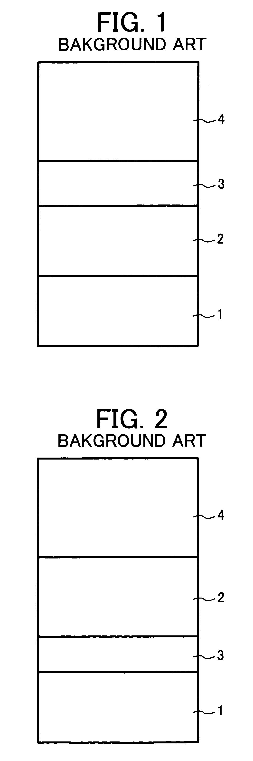
However, when the electroconductive layer 2 has a relatively high resistance, charges are not well injected from the electroconductive substrate 1, and the resistance of the layer 2 increases after long repeated use, thereby increasing the residual potential of the photoreceptor.
In this case, the residual potential increasing problem remarkably occurs.
However, the crystal form and the primary particle diameter of the titanyl phthalocyanine crystal are not controlled.
Therefore, occurrence of the background development problem due to the hot carriers cannot be prevented.
If a proper charge generation material is not used for the charge generation layer and the conditions of the particles of the charge generation material are not properly controlled, occurrence of the background development problem cannot be prevented.

Method used


Image

  • Electrophotographic photoreceptor, method for manufacturing the electrophotographic photoreceptor, and image forming apparatus and process cartridge using the electrophotographic photoreceptor
  • Electrophotographic photoreceptor, method for manufacturing the electrophotographic photoreceptor, and image forming apparatus and process cartridge using the electrophotographic photoreceptor
  • Electrophotographic photoreceptor, method for manufacturing the electrophotographic photoreceptor, and image forming apparatus and process cartridge using the electrophotographic photoreceptor

Examples


synthesis example 1

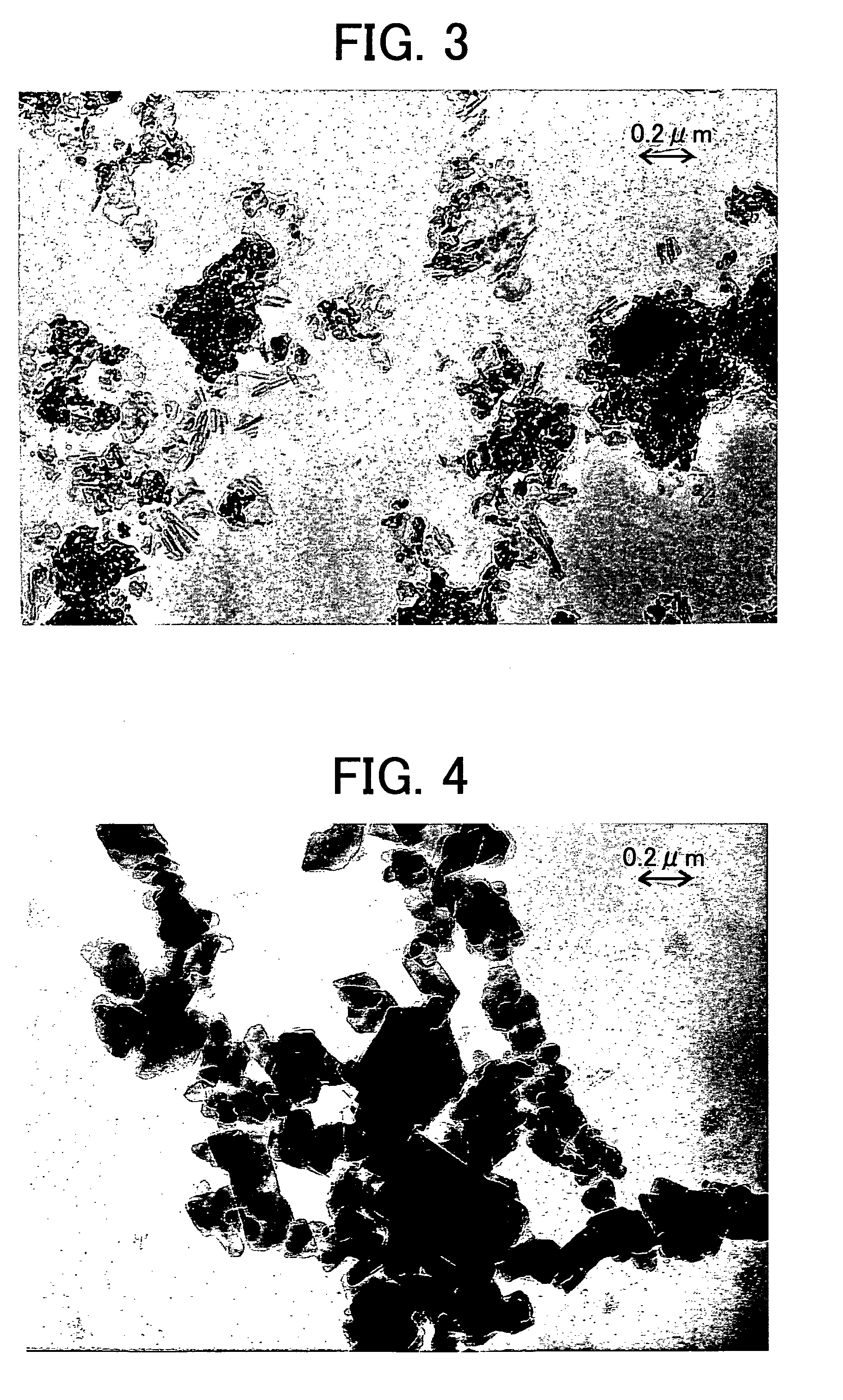
[0321]The procedure for preparation of the aqueous wet cake in Comparative Synthesis Example 1 was repeated. Then the pigment was subjected to the crystal change treatment mentioned below, to prepare a titanyl phthalocyanine crystal having a primary particle diameter smaller than that of the crystal prepared in Comparative Synthesis Example 1.

[0322]Specifically, 60 g of the aqueous wet paste, which had not been subjected to a crystal change treatment and which has a solid content of 15% by weight, was mixed with 400 g of tetrahydrofuran (THF) and the mixture was strongly agitated at room temperature using a homomixer MARK IIf model manufactured by Kenis Ltd., whose rotor was rotated at a revolution of 2,000 rpm. In this case, the ratio of the pigment to the crystal change solvent (THF) was 1:44. When the color of the paste was changed from dark blue to light blue (20 minutes after the start of agitation), the agitation was stopped, and the dispersion was filtered under a reduced pre...

preparation example 1

Dispersion Preparation Example 1

[0331]A dispersion having the following formula was prepared using the titanyl phthalocyanine pigment 1 prepared in Comparative Synthesis Example 1.

[0332]

Titanyl phthalocyanine pigment 1 15 partsPolyvinyl butyral 10 parts(S-LEC BX-1 from SekisuiChemical Co., Ltd.)2-butanone280 parts

[0333]At first, the polyvinyl butyral resin was dissolved in 2-butanone. Then titanyl phthalocyanine pigment 1 was dispersed for 30 minutes in the resin solution using a dispersion machine including PSZ balls with a particle diameter of 0.5 mm while the rotor was rotated at a revolution of 1200 rpm. Thus, a dispersion 1 was prepared.

Dispersion Preparation Examples 2-9

[0334]The procedure for preparation of the dispersion 1 in Dispersion Preparation Example 1 was repeated except that titanyl phthalocyanine pigment 1 was replaced with titanyl phthalocyanine pigments 2-9. Thus, dispersions 2-9 were prepared.

preparation example 10

Dispersion Preparation Example 10

[0335]The dispersion 1 prepared in Dispersion Preparation Example 1 was subjected to filtering using a cotton wind cartridge filter TCW-1-CS with an effective pore diameter of 1 μm, which is manufactured by ADVANTECH, while applying a pressure using a pump. Thus, a dispersion 10 was prepared.


PUM


Abstract

A photoreceptor including an electroconductive substrate; and a charge blocking layer; a moiré preventing layer; and a photosensitive layer, which are overlaid overlying the substrate in this order, wherein the photosensitive layer includes a titanyl phthalocyanine crystal which has an average primary particle diameter not greater than 0.25 μm, and has an X-ray diffraction spectrum such that a maximum peak is observed at a Bragg (2θ) angle of 27.2°±0.2°; a peak is observed at Bragg (2θ) angle of 9.4°±0.2°, 9.6±0.2° and 24.0±0.2°; a lowest angle peak is observed at an angle of 7.3°±0.2°; no peak is observed between the lowest angle peak and the 9.4° peak; and no peak is observed at a Bragg (2θ) angle of 26.3°±0.2°, when a Cu—Kα X-ray having a wavelength of 0.1542 nm (1.542 Å) is used.

Description

BACKGROUND OF THE INVENTION[0001]1. Field of the Invention[0002]The present invention relates to an electrophotographic photoreceptor. Particularly the present invention relates to an electrophotographic photoreceptor having a photosensitive layer including a titanyl phthalocyanine crystal. In addition, the present invention also relates to a method for manufacturing the photoreceptor, and an image forming apparatus and a process cartridge using the electrophotographic photoreceptor.[0003]2. Discussion of the Background[0004]Recently, development of information processing systems utilizing electrophotography is remarkable. In particular, optical printers in which information is converted to digital signals and then the information is recorded using light have been dramatically improved in print qualities and reliability. This digital recording technique is applied to not only printers but also copiers, and so-called digital copiers have been developed. Copiers utilizing both the con...

Claims


Application Information

Patent Timeline
Patent Type & Authority Patents(United States)
IPC IPC(8): G03G5/047G03G5/14G03G5/06
CPCG03G5/0696G03G5/142G03G5/144
Inventor NIIMI, TATSUYATAMOTO, NOZOMUOHTA, KATSUICHI
Owner RICOH KK
Learn More