
Motion control mechanism for a piston engine

Inactive Publication Date: 2008-05-20
JONIEC ALEXANDER F
View PDF11 Cites 26 Cited by
  • Summary
  • Abstract
  • Description
  • Claims
  • Application Information

AI Technical Summary

Benefits of technology

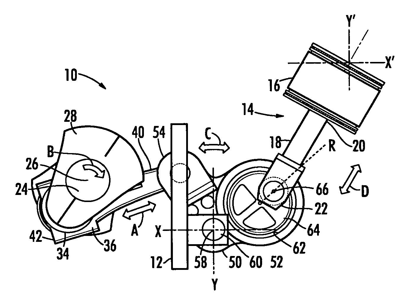
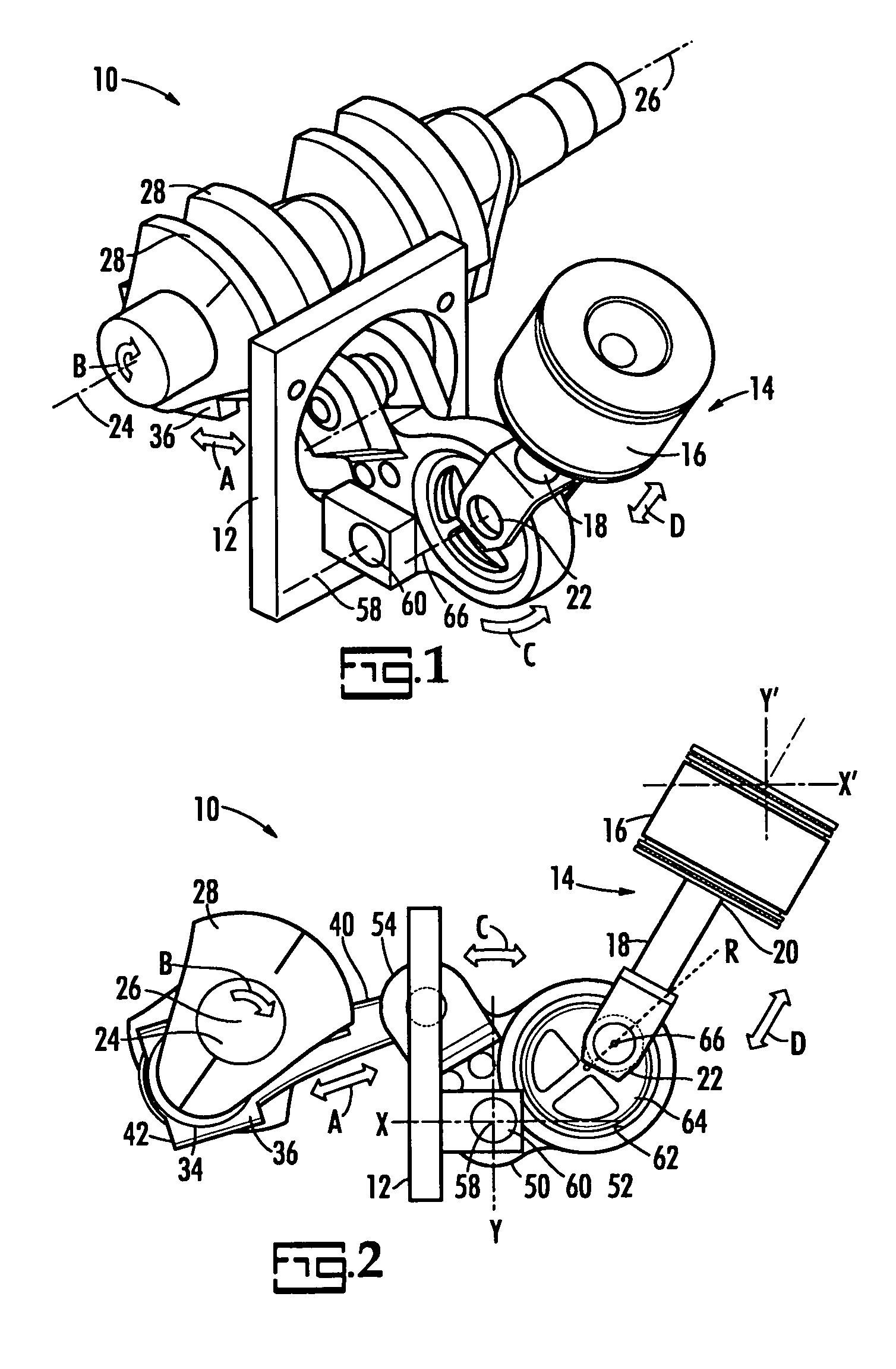
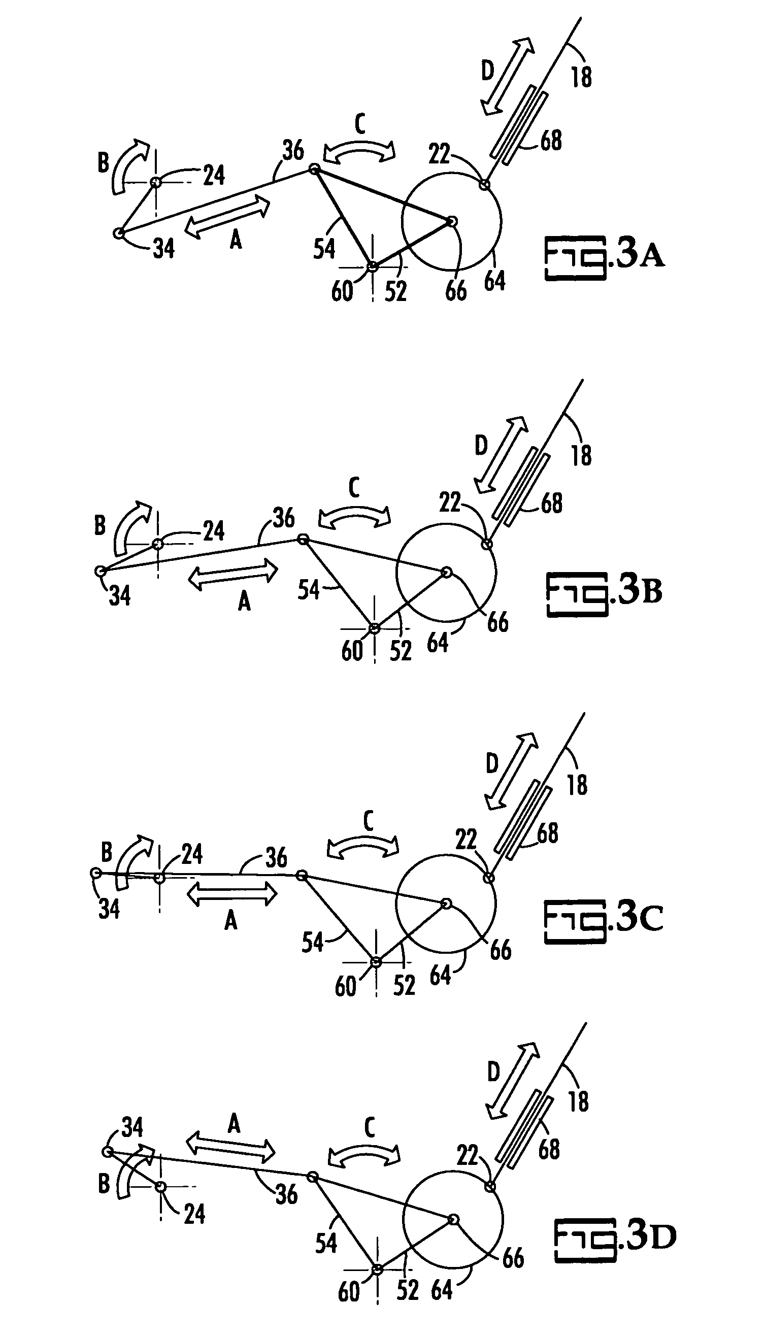
[0007]According to its major aspects and briefly recited, the present invention is an improved piston engine, and a piston engine improved by the addition of a mechanism that allows the relationship between piston motion and crankshaft motion to be altered from that of the classic piston engine so that the limitations of that engine are overcome and more power can be realized when using the same fuel energy. By inserting basically two main components between the end of a rigidly attached piston rod and the crankshaft, namely, a unique rocker arm and a connecting link, the motion of the piston with respect to the crankshaft can be altered in important ways, ways that allow a more efficient transfer of energy between the moving piston and the rotating crankshaft over the classic crankshaft and connecting rod configuration.
[0008]In addition there are three areas of improvement that are also included in this invention. 1. By not having the piston move while combustion is taking place, the combustion chamber shape can be better optimized. 2. Substantially less additional surface area is exposed during the combustion process and power stroke to lose heat energy too. 3. Due to the unique configuration and method of the component placement, the invention permits different placement of the crankshaft TDC and the piston TDC which permits the TDC cylinder pressure to effectively leverage it into producing useful torque both sooner in the power stoke and with more advantageous rod angle that produces more torque at the same cylinder pressure.
[0010]The increase in efficiency is more than enough to compensate for the additional friction of these components introduce, and comes from several sources. First, the rate of travel of a piston with respect to the different segments of its cycle can be altered from that of a classic piston engine. For example, the rate of travel can be made slower at the top of the cycle and faster at the bottom, the opposite of prior art piston engines, or made the same speed at both of the cycle top and bottom. The present design allows the rate of piston travel to be adjusted to achieve the designer's requirements. When slowed as the piston moves toward top dead center, both less fuel in needed and the combusting fuel has more time to build pressure with a smaller combustion chamber volume as the result of the piston not moving during the combustion process. In a standard piston engine, the gas is still combusting as the piston is well-along in its down stroke. Accordingly, the pressure does not build to the same levels of PSI as in the present invention. In addition the present invention maintains a higher cylinder pressure over a longer period of optimum crankshaft travel of the first 45 degrees of the power stroke, for a higher average PSI when starting with the same PSI as a classic configuration.
[0011]A piston engine according to the present invention can be designed to slow or even pause in the movement of the piston so that combustion has a chance to go to completion before the cylinder travels very far from top dead center. Moreover, the present mechanism allows the cylinder to fire when the engine designer wants the cylinder to fire, including in advance of top dead center, for maximum pressure if so desired. When timing the firing before top dead center using the present invention, there is little to no negative work being done as the piston is already at or near TDC and does not have to oppose any pressure as in a classic engine design.
[0013]In addition to increases in efficiency, the present system and method makes new arrangements of engines possible by taking advantage of the possible orientations of piston to crankshaft.

Problems solved by technology

First, adding additional parts, with their inherent contributions to the friction of the system would be expected to reduce overall efficiency.

Method used


Image

  • Motion control mechanism for a piston engine
  • Motion control mechanism for a piston engine
  • Motion control mechanism for a piston engine

Examples


Embodiment Construction

[0029]The present invention is an improved engine. The present invention improves that prior art, or “classic,” piston / crankshaft arrangement that is a part of many engines and pumps. The improvement, as will be explained in more detail below, comprises the insertion of two components between the piston rod and the crankshaft in order to allow the engine designer to alter the geometric relationship between the piston and the crankshaft, and, with that altered geometry, the mechanical performance characteristics of the engine or pump. In particular, the engine designer can change the piston stroke length, the overall rate of travel of the piston, the instantaneous rates of piston movement as it goes through its cycle so that some portions of the travel are slower and others faster than before, and change the angle between the direction of piston motion (coincident with the long axis of the piston) and a line perpendicular to the axis of the crankshaft.

[0030]By slowing the relative ra...


PUM


Abstract

An improved piston engine includes a rocker arm and a connecting link between the piston rod and the crankshaft to allow its motion to be altered from that of the classic piston engine in order to overcome inherent limitations of the latter and realize greater efficiency. By inserting these two components between the end of a rigidly attached piston rod and a conventional crankshaft, the motion of the piston with respect to the crankshaft can be altered in important ways. For example, the dwell at top dead center can be increased relative to dwell at bottom dead center to the point where they are equal or in fact where dwell at top dead center is greater. Furthermore, because the piston rod is not directly connected to the crankshaft, ignition of the fuel can be timed to occur before top dead center so that pressure is maximized at top dead center in order to improve efficiency. Furthermore, the piston stroke can be shortened and slowed by the geometry of the rocker arm, thus increasing engine life.

Description

CROSS REFERENCE TO RELATED PATENTS[0001]Not applicable.BACKGROUND OF THE INVENTION[0002]The present invention relates to a motion control system and method for use in converting reciprocating motion of a piston to a more efficient rate of travel in proportion to crankshaft travel. This system and method are applicable to all known classic reciprocating internal combustion engines, external combustion steam engines, and can be used to integrate pneumatic and hydraulic pumps into the design.[0003]The piston and crankshaft have been an important part of engines and pumps for scores of years. Numerous improvements have been made to the classic piston engine, including better materials, better lubricants, and improved fuel injection systems. However certain problems remain that are inherent in the classic piston engine. These problems arise because of geometrical limitations on the relationship between the piston and the crankshaft of the conventional piston engine.[0004]In typical recip...

Claims


Application Information

Patent Timeline
IPC IPC(8): F02B75/32F02B75/04
CPCF02B75/048F02B75/32Y10T74/18176F02B2275/36
Inventor JONIEC, ALEXANDER F.
Owner JONIEC ALEXANDER F
Learn More