Adsorption filter and manufacturing method thereof

a technology of adsorption filter and manufacturing method, which is applied in the direction of filtration separation, separation process, dispersed particle separation, etc., can solve the problems of metal corrosion, gaseous contaminants such as amines are also generated, and fogging is caused

Inactive Publication Date: 2008-05-27
NICHIAS CORP
View PDF12 Cites 24 Cited by
  • Summary
  • Abstract
  • Description
  • Claims
  • Application Information

AI Technical Summary

Benefits of technology

[0016]The foregoing objects of the present invention have been achieved by providing the following adsorption filters and manufacturing method.
[0018]at least one thin plate honeycomb filtering medium carrying a gas-adsorbing medium thereon; and
[0020]wherein the thin plate honeycomb filtering medium is disposed in the filter case in such a manner as to make a series of V configurations with respect to a ventilation direction.
[0021]With the adsorption filter having this configuration, V-shaped disposition results in an increase in filter effective surface area relative to the filter case opening area. Therefore, the pressure loss of the adsorption filter is reduced as compared to the case where ventilation is effected perpendicular to the filter. This adsorption filter is adaptable to high wind velocity (1 m / s to 3 m / s).
[0022]2) The adsorption filter according to the item 1) above, wherein the series of V configurations is formed by one thin plate honeycomb filtering medium carrying a gas-adsorbing medium thereon.

Problems solved by technology

Further, it is known that basic gaseous contaminants such as amines are also generated from the construction materials of a clean room or the chemicals for processing.
Further, they react with an acidic gas, thereby to form a salt, so that fogging is caused on the surface of an optical component of a processing device or a silicon wafer.
On the other hand, when acidic gaseous contaminants are present in a clean room, they corrode the glass fiber of a dust collecting filter, thereby to promote the generation of boron, and to bring about a metal corrosion of IC or the like.
This inevitably results in a high wind velocity in the duct.
Accordingly, a small thickness filter provides a short contact time (residence time) with the air to be treated, so that a sufficient removing performance cannot be obtained.
When the filter thickness is increased in order to increase the residence time, the pressure loss increases.
This unfavorably causes problems of necessitating an increased capacity of an air blower, an increased blowing energy, and the like.
In this case, there are the following problems: the powder falling amount and the generated dust amount are large, resulting in a contamination in a clean room; the weight is very large because an activated carbon is filled therein; framing of the filter is time-consuming; the total weight has been increased by the weight of the cassette frame; and other problems.
A corrugated spacer for shape keeping, or a hard porous material such as a web made of a metal or made of a hard plastic or a punching metal is generally used therefor, which causes an increase in pressure loss.
Further, there is also another problem as follows: an air does not flow through the crest and valley portions of the folds, so that the filter is not consumed uniformly (see Patent Document 3).
Furthermore, assembling is not easy, so that the corrugated spacer and the hard porous material become industrial wastes upon disposal (see Patent Document 2).

Method used


Image

  • Adsorption filter and manufacturing method thereof
  • Adsorption filter and manufacturing method thereof
  • Adsorption filter and manufacturing method thereof

Examples


example 1

Manufacturing of Adsorption Filter

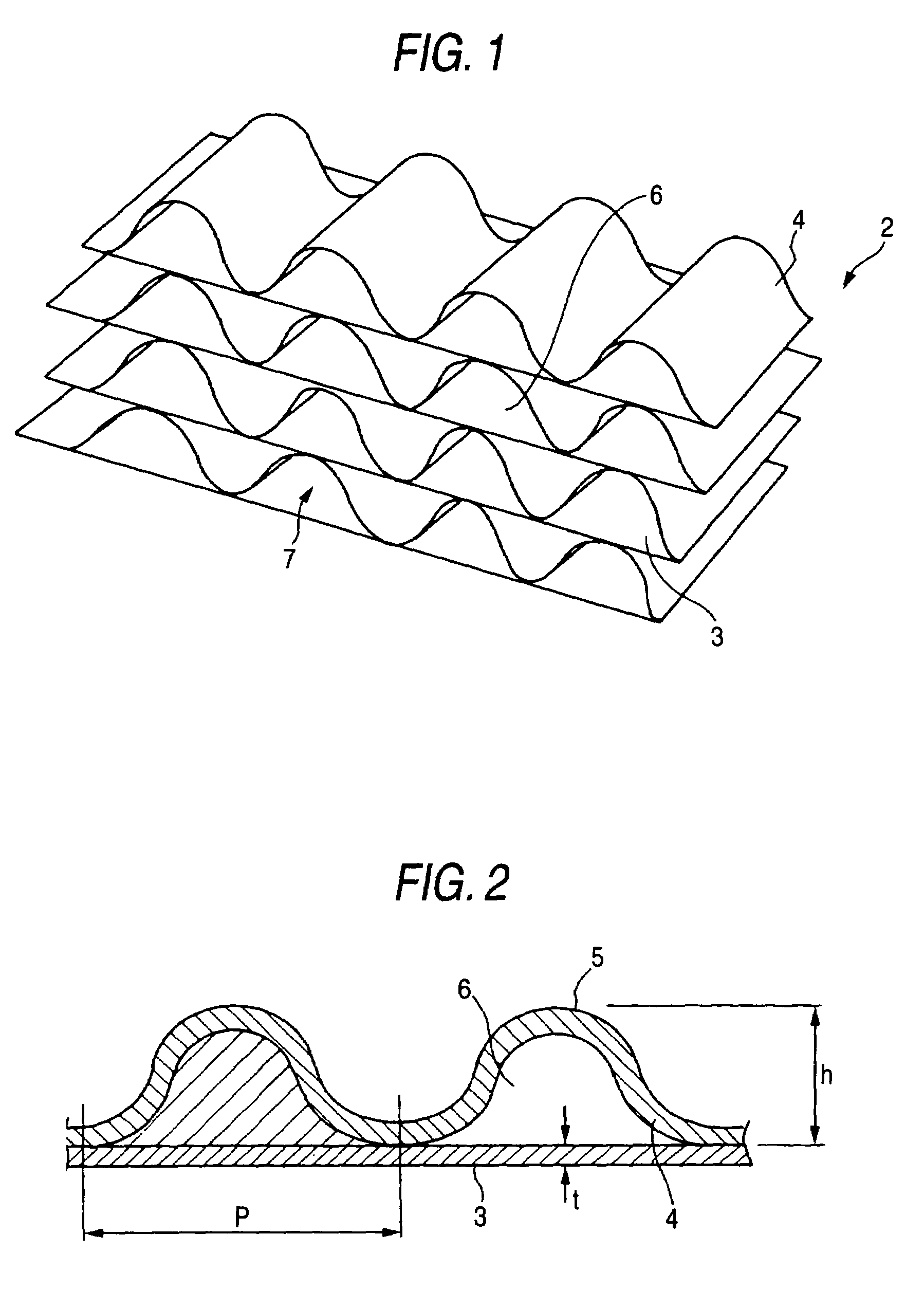
[0121]On the top surface of a flat fibrous substrate 3 (see FIG. 1) made of a silica / alumina fiber (average fiber diameter 50 mm, average fiber length 20 mm), and having an interfiber porosity of 90% and a thickness of 0.2 mm, a suspension containing a powdered activated carbon and an acrylic type copolymer binder was coated so that the amount of activated carbon carried was 90 g / m2. After drying, the substrate 3 was treated at a temperature of 110° C. to manufacture an activated carbon-coated substrate.

[0122]The activated carbon-coated substrate was divided into a portion to be corrugated and a portion not to be corrugated. The portion to be corrugated was caused to pass through a pair of upper and lower corrugated rolls, thereby obtaining a corrugated product 4. An acrylic type copolymer binder was applied to the crest portions (see FIG. 2) of the corrugated product 4. The flat product 3 not corrugated was stacked thereon for lamination, thereby f...


PUM

PropertyMeasurementUnit
velocityaaaaaaaaaa
porosityaaaaaaaaaa
diameteraaaaaaaaaa

Abstract

An adsorption filter includes at least one thin plate honeycomb filtering medium carrying a gas-adsorbing medium thereon and a filter case housing the honeycomb filtering medium therein. The thin plate honeycomb filtering medium is disposed in the filter case in such a manner as to make a series of V configurations with respect to a ventilation direction.

Description

FIELD OF THE INVENTION[0001]The present invention relates to a adsorption filter for removing gaseous contaminants such as very low concentration acidic gaseous contaminants, basic gaseous contaminants, and TOC (Total Organic Compound), generated from the human body or generated during a manufacturing process in a clean room of, for example, a semiconductor-manufacturing plant or a precision electronic devices-manufacturing plant, and a manufacturing method thereof.BACKGROUND OF THE INVENTION[0002]In the leading-edge industries of semiconductor manufacturing / liquid crystal manufacturing, and the like, it is important to control the contamination of the air or the product surface in a clean room in order to ensure the yield, quality, and reliability of a product. In particular, in the semiconductor industry field, control of an ionic gaseous contaminant becomes indispensable in addition to the control of a particulate contaminant using a HEPA (High Efficiency Particulate Air) filter,...

Claims


Application Information

Patent Timeline
Patent Type & Authority Patents(United States)
IPC IPC(8): B01D53/02B01D39/00B01D39/14B01D39/20B01D53/04
CPCB01D46/526B01D53/02B01D2251/40B01D2251/50B01D2251/60B01D2253/102B01D2253/108B01D2253/206B01D2253/25B01D2253/311B01D2253/3425B01D2257/70B01D2258/0216B01D53/04B01D39/00B01D39/20
Inventor TANAHASHI, TAKASHIIMAI, AKIHIRONAKANO, TOSHIROTANIGUCHI, TAKASHI
Owner NICHIAS CORP
Why Eureka
Try Eureka