
Device for pressurized perfusion especially for culturing and/or treating cells

a technology of pressurized perfusion and cell, applied in the field of bioreactors, can solve the problems of high design requirements, membrane breakage, and movement patterns that impart high mechanical stress to the membrane structure, and achieve the effect of low energy consumption and high degree of parallelization

Inactive Publication Date: 2008-05-27
BADER AUGUSTINUS
View PDF39 Cites 20 Cited by
  • Summary
  • Abstract
  • Description
  • Claims
  • Application Information

AI Technical Summary

Benefits of technology

[0009]The task of the present invention is to provide a device without the above-described disadvantages. An object of the invention is to provide a possibility for generating physiological, homogeneously acting pressure and volume amplitudes equally in a volumetric flow of liquid. Specifically, an object of the invention is to make it possible to generate entirely homogeneous pressure relations in all areas also in the bioartificial tissue within the bioreactor. The device is to be variably adaptable to the pressure-volume compliance of the system to be perfused. The device is to be modular, small, weight-saving, reliable, of low energy consumption and able to be coupled or combined with any systems to be perfused and is to apply minimal mechanical stress or no mechanical stress at all to the volumetric flow so that it can be connected with blood or other stress-sensitive fluids with or without biological components such as cells or proteins. Another object of the invention is to achieve a high degree of parallelization in the smallest space to be obtained by miniaturizing the module and by the direct ability to be coupled to and integrated in any possible perfusion systems.

Problems solved by technology

This implies not only high design requirements, but such load does not reflect in-vivo conditions due to the heterogeneous pressure distribution such obtained.
But this is unphysiological, because no such perfusions are encountered e.g. in articulation areas.
A disadvantage to said movement processes is that the movement patterns impart high mechanical stress to the membrane structures.
That causes the membranes to break after a few days and makes the products insterile and thus inappropriate for implantations.
Furthermore, due to the movement patterns permanently causing convex-concave deformations, the membranes can only generate punctual and thus inhomogeneously distributed pressure deformations.
Such models are a sophisticated design and expensive to sell, because the pumping system, due to its integration in the bioreactor, must be shipped with the future bioimplant as a complete unit.
That is especially disadvantageous if different medium compositions are needed inside and outside the vessels, e.g. to be able to offer growth factors and chemotactic factors directionally.
That prevents e.g. the induction of directed migration of myofibroblasts from the place of population towards the outsides and constitutes a significant disadvantage in the population process.
Another disadvantage is immediate pressure compensation, which makes it impossible to create different pressure profiles in the intravascular and extravascular spaces.
However, the pulsatile or pulse-type flow is in most cases generated in a conventional way via a peristaltic pump such that the pressure amplitudes are rather low in terms of change in volume, show flat frequencies and also mean high stress loads for the hose during several weeks' operation due to the permanent kneading effect.

Method used


Image

  • Device for pressurized perfusion especially for culturing and/or treating cells
  • Device for pressurized perfusion especially for culturing and/or treating cells
  • Device for pressurized perfusion especially for culturing and/or treating cells

Examples


Embodiment Construction

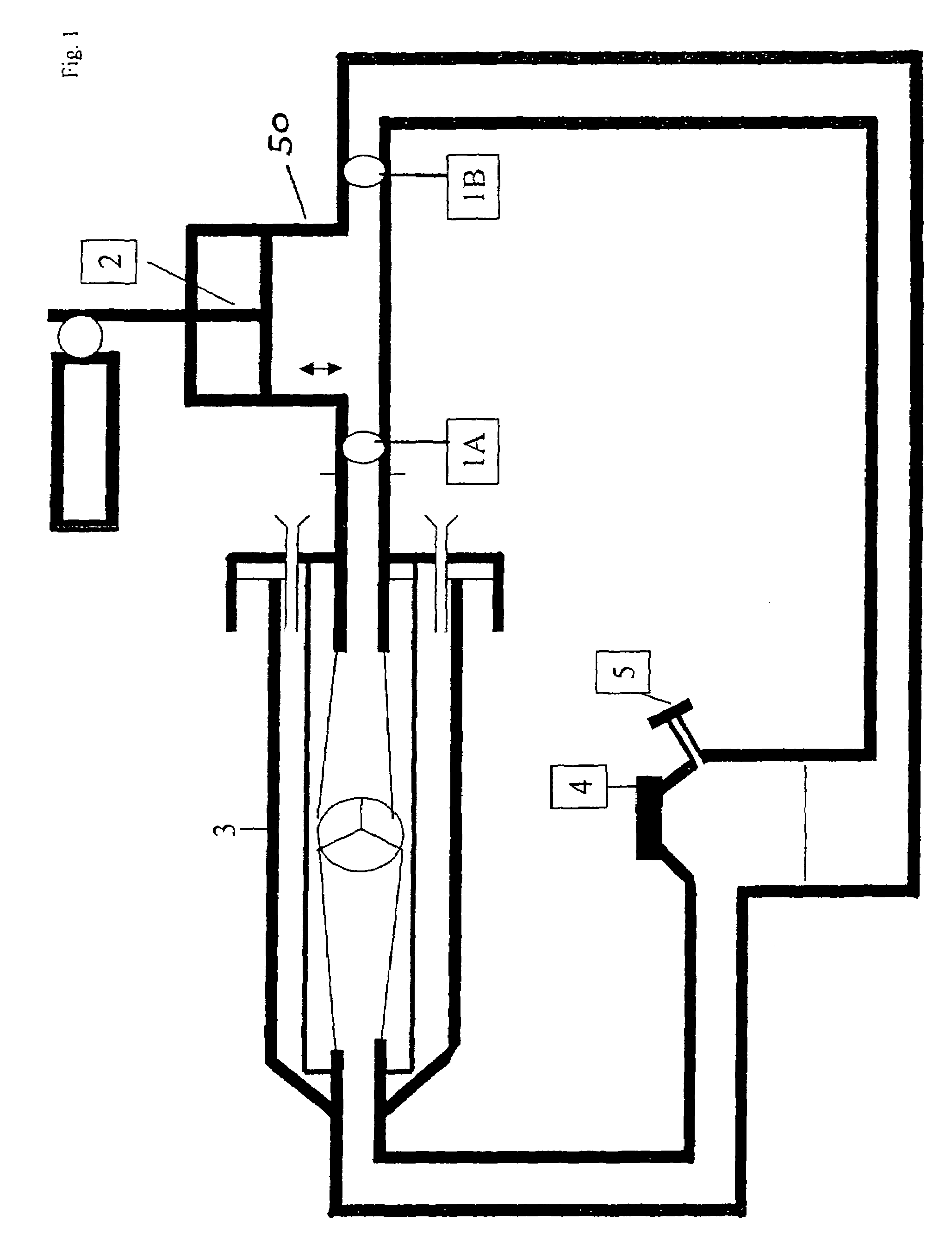
[0030]FIG. 1 shows a modular component, which is coupled to a bioreactor 3. The module is composed of two valves 1A and 1B as well as of a piston 2 and is adaptable to the bioreactor via a sterile coupling and directly, as shown in FIG. 1, integratable in the influence area. Both valves 1A and 1B open in the same direction, in FIG. 1 to the left, towards the bioreactor. This generates a volumetric flow which is introduced into the reactor area at a high amplitude and pressure curve. So it is possible to achieve the opening and closing of an implant placed in the bioreactor, e.g. an allogenic heart valve. Two-leaflet valves opening or closing passively from flow changes are especially suited for the valves 1A and 1B. Other non-return valves, such as balls in a conically tapered tube section, are also possible.

[0031]FIG. 1 shows the perfusion module in a sagitally directed form. The advantage is that the backward movement of the piston 2 across the opening of valve 1A enhancedly cause...


PUM

PropertyMeasurementUnit
volumeaaaaaaaaaa
volumeaaaaaaaaaa
weightaaaaaaaaaa

Abstract

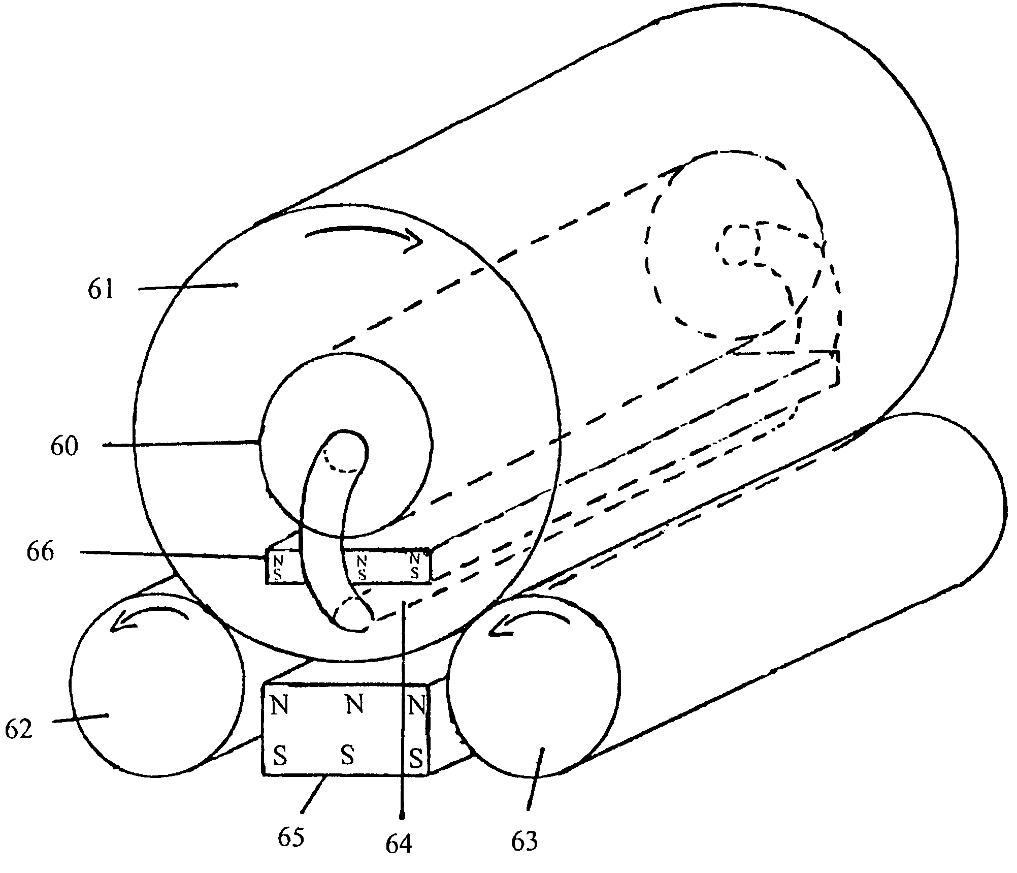
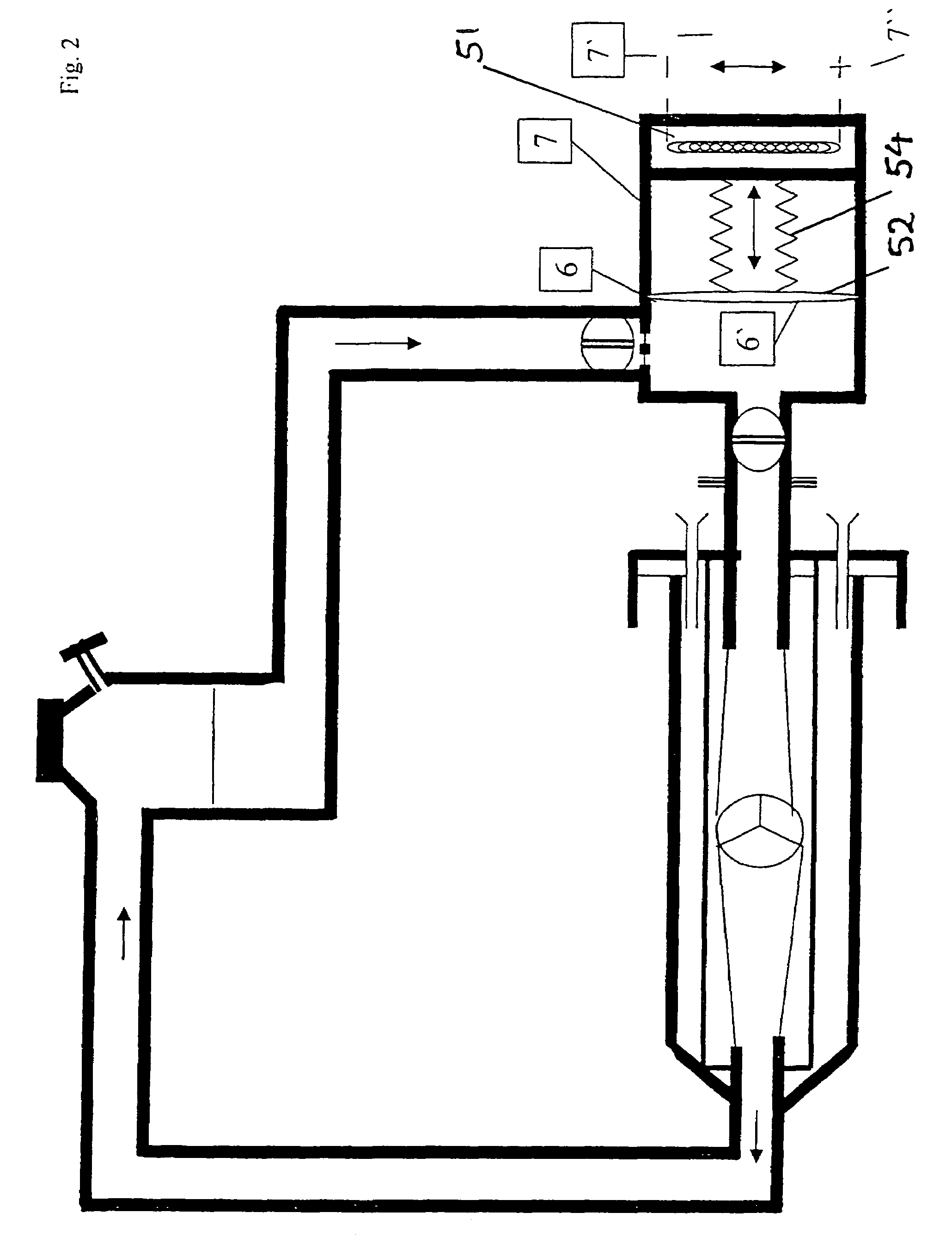
The invention relates to a device for pumping a fluid into a bioreactor. Polsatile pumping is made possible by valve arrangement so that growth of the cells in the bioreactor is increased. Pumping function can be achieved though several mechanisms. A piston can be displaced in a cylinder, especially by an electromagnet, wherein a permanent magnet or likewise an electromagnet can be arranged in the piston. The piston can also be displaced by compressed air. An elastic, hollow body can also be provided, wherein said hollow body can be deformed by mechanical electromagnetic forces so that pumping function is achieved by a change in volume. The pumping device can also be used as implant for assisting or replacing heart function.

Description

TECHNICAL FIELD[0001]The invention relates to a device for cultivating and / or treating cells, especially a bioreactor. Furthermore, the invention relates to a device for pumping a fluid through a device for cultivating and / or treating cells, especially through a bioreactor.[0002]A method and a device of the initially mentioned type is described in an older application of the inventor DE 199 35 643.2.[0003]Meanwhile, it has been found that the formation of a cell layer and cell growth are clearly improved by putting cells under pressure. A known practical approach is to apply a mechanical force to a cell culture chamber, e.g. by a plunger, as described in U.S. Pat. No. 6,060,306. This implies not only high design requirements, but such load does not reflect in-vivo conditions due to the heterogeneous pressure distribution such obtained. The attempt made in U.S. Pat. No. 5,928,945 is to apply a mechanical force e.g. to cartilage cells chiefly via shear flow stress by means of a cultur...

Claims


Application Information

Patent Timeline
Patent Type & Authority Patents(United States)
IPC IPC(8): C12M1/00C12M1/10C12M3/04F04B9/127F04B17/04F04B43/09F04B43/10H02K33/16
CPCC12M29/10C12M29/12C12M35/04F04B9/127F04B17/044F04B43/09F04B43/10H02K33/16
Inventor BADER, AUGUSTINUS
Owner BADER AUGUSTINUS
Learn More