Source material dispenser for EUV light source

a source material dispenser and light source technology, applied in the field of extreme ultraviolet (“ euv”) light source, can solve the problems of reducing the operational efficiency of the various plasma chamber optical elements, clogging of the nozzle, and affecting the flow of source materials, so as to reduce the flow of hea

Active Publication Date: 2008-05-27
ASML NETHERLANDS BV
View PDF181 Cites 53 Cited by
  • Summary
  • Abstract
  • Description
  • Claims
  • Application Information

AI Technical Summary

Benefits of technology

[0013]In a first aspect, a source material dispenser for an EUV light source is disclosed that comprises a source material reservoir, e.g. tube, that has a wall and is formed with an orifice. The dispenser may further comprise an electro-actuatable element that is spaced from the wall and operable to deform the wall and modulate a release of source material from the dispenser. A heat source heating a source material in the reservoir may be provided. Also, the dispenser may comprise a heat insulator reducing the flow of heat from the heat source to the electro-actuatable element.

Problems solved by technology

In addition to generating EUV radiation, these plasma processes also typically generate undesirable by-products in the plasma chamber (e.g debris) which can potentially damage or reduce the operational efficiency of the various plasma chamber optical elements.
Another factor that must be considered is nozzle clogging.
Clogging can disturb the flow of source material through the nozzle, in some cases causing droplets to move along a path that is at an angle to the desired droplet trajectory.
Manually accessing the nozzle for the purpose of unclogging it can be expensive, labor intensive and time-consuming.
In particular, these systems typically require a rather complicated and time consuming purging and vacuum pump-down of the plasma chamber prior to a re-start after the plasma chamber has been opened.
This lengthy process can adversely affect production schedules and decrease the overall efficiency of light sources for which it is typically desirable to operate with little or no downtime.

Method used


Image

  • Source material dispenser for EUV light source
  • Source material dispenser for EUV light source
  • Source material dispenser for EUV light source

Examples


Embodiment Construction

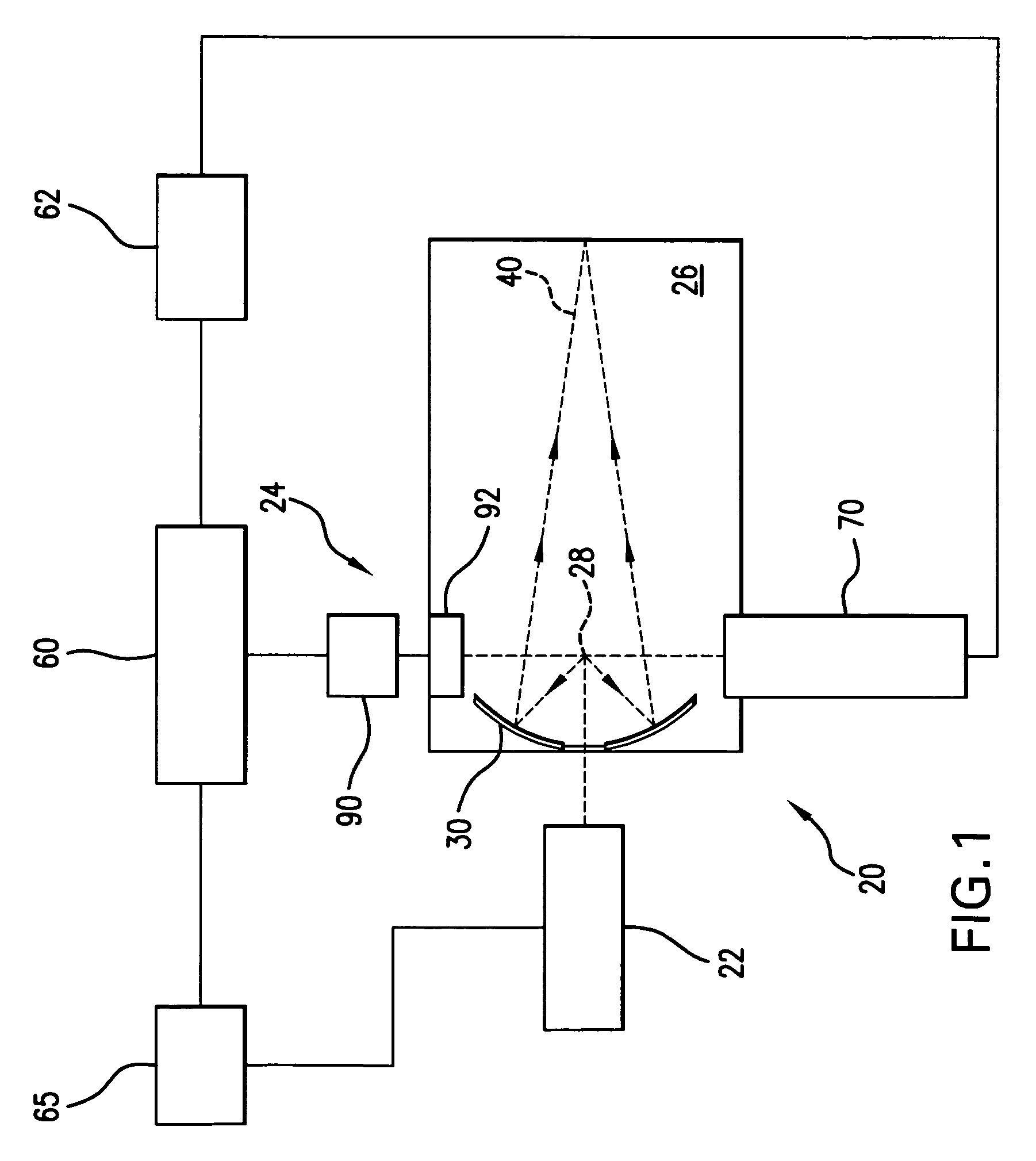
[0026]With initial reference to FIG. 1 there is shown a schematic view of an exemplary EUV light source, e.g., a laser produced plasma EUV light source 20 according to an aspect of the present invention. As shown, the LPP light source 20 may contain a pulsed or continuous laser system 22, e.g., a pulsed gas discharge CO2, excimer or molecular fluorine laser operating at high power and high pulse repetition rate. Depending on the application, other types of lasers may also be suitable. For example, a solid state laser, a MOPA configured excimer laser system, e.g., as shown in U.S. Pat. Nos. 6,625,191, 6,549,551, and 6,567,450, an excimer laser having a single chamber, an excimer laser having more than two chambers, e.g., an oscillator chamber and two amplifying chambers (with the amplifying chambers in parallel or in series), a master oscillator / power oscillator (MOPO) arrangement, a power oscillator / power amplifier (POPA) arrangement, or a solid state laser that seeds one or more CO...


PUM


Abstract

A source material dispenser for an EUV light source is disclosed that comprises a source material reservoir, e.g. tube, that has a wall and is formed with an orifice. The dispenser may comprise an electro-actuatable element, e.g. PZT material, that is spaced from the wall and operable to deform the wall and modulate a release of source material from the dispenser. A heat source heating a source material in the reservoir may be provided. Also, the dispenser may comprise an insulator reducing the flow of heat from the heat source to the electro-actuatable element. A method of dispensing a source material for an EUV light source is also described. In one method, a first signal may be provided to actuate the electro-actuatable elements to modulate a release of source material and a second signal, different from the first, may be provided to actuate the electro-actuatable elements to unclog the orifice.

Description

[0001]The present application is a continuation-in-part application of co-pending U.S. patent application Ser. No. 11 / 067,124 filed on Feb. 25, 2005, entitled METHOD AND APPARATUS FOR EUV PLASMA SOURCE TARGET DELIVERY, attorney docket number 2004-0008-01, the entire contents of which are hereby incorporated by reference herein.[0002]The present application is also a continuation-in-part application of co-pending U.S. patent application Ser. No. 11 / 174,443 filed on Jun. 29, 2005, entitled LPP EUV PLASMA SOURCE MATERIAL TARGET DELIVERY SYSTEM, attorney docket number 2005-0003-01, the entire contents of which are hereby incorporated by reference herein.[0003]The present application is also related to co-pending U.S. non-provisional patent application entitled LASER PRODUCED PLASMA EUV LIGHT SOURCE WITH PRE-PULSE filed concurrently herewith, Ser. No. 11 / 358988, the entire contents of which are hereby incorporated by reference herein.[0004]The present application is also related to co-pe...

Claims


Application Information

Patent Timeline
Patent Type & Authority Patents(United States)
IPC IPC(8): H01J35/20
CPCH05G2/003H05G2/006H05G2/005
Inventor BYKANOV, ALEXANDER N.KHODYKIN, OLEH
Owner ASML NETHERLANDS BV
Why Eureka
Try Eureka