Electrostatic latent image read-out method and apparatus
a technology of latent image and read-out method, which is applied in the direction of conversion screens, instruments, nuclear engineering, etc., can solve the problems of low signal-to-noise ratio of the signal obtained from exposure scanning, low capacity of the electrostatic recording material, and low signal-to-noise ratio of the signal, so as to achieve enhanced signal-to-noise ratio, the effect of keeping high throughput of the signal-to-noise ratio of the obtained signal
- Summary
- Abstract
- Description
- Claims
- Application Information
AI Technical Summary
Benefits of technology
Problems solved by technology
Method used
Image
Examples
first embodiment
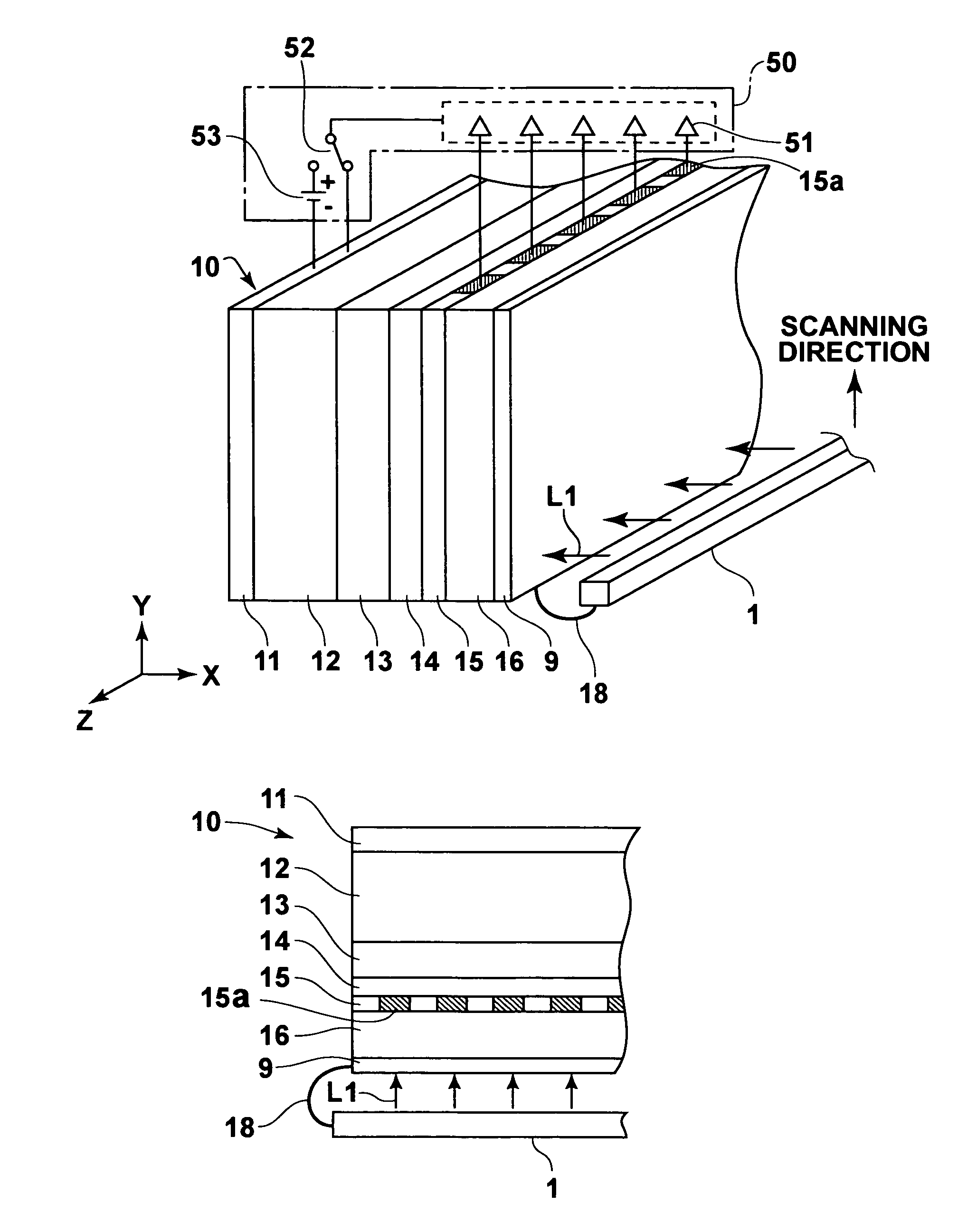
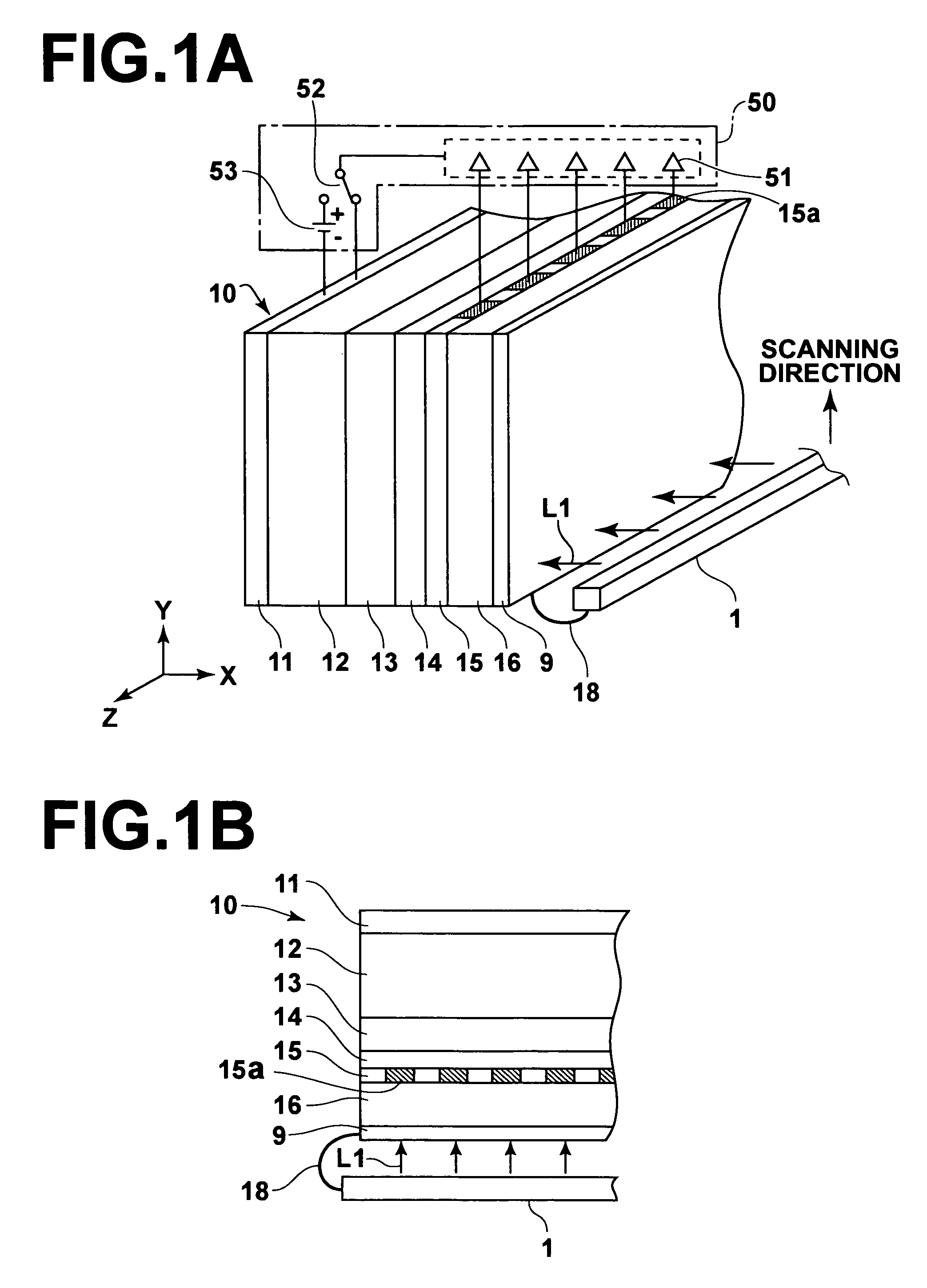
[0058]FIG. 1A is a perspective view showing the electrostatic latent image read-out apparatus in accordance with the present invention. FIG. 1B is an X-Z cross-sectional view of FIG. 1A. As illustrated in FIG. 1A, the electrostatic latent image read-out apparatus comprises an electrostatic recording material 10. The electrostatic latent image read-out apparatus also comprises a reading light source 1 for irradiating reading light L1 to the electrostatic recording material 10 at the time of readout of image information from the electrostatic recording material 10. The electrostatic latent image read-out apparatus further comprises an indium tin oxide (ITO) film 9, which is formed over the entire area of the surface of the electrostatic recording material 10, which surface stands facing the reading light source 1. The electrostatic latent image read-out apparatus still further comprises current detecting means 50 for detecting electric currents, which flow out from the electrostatic r...
second embodiment
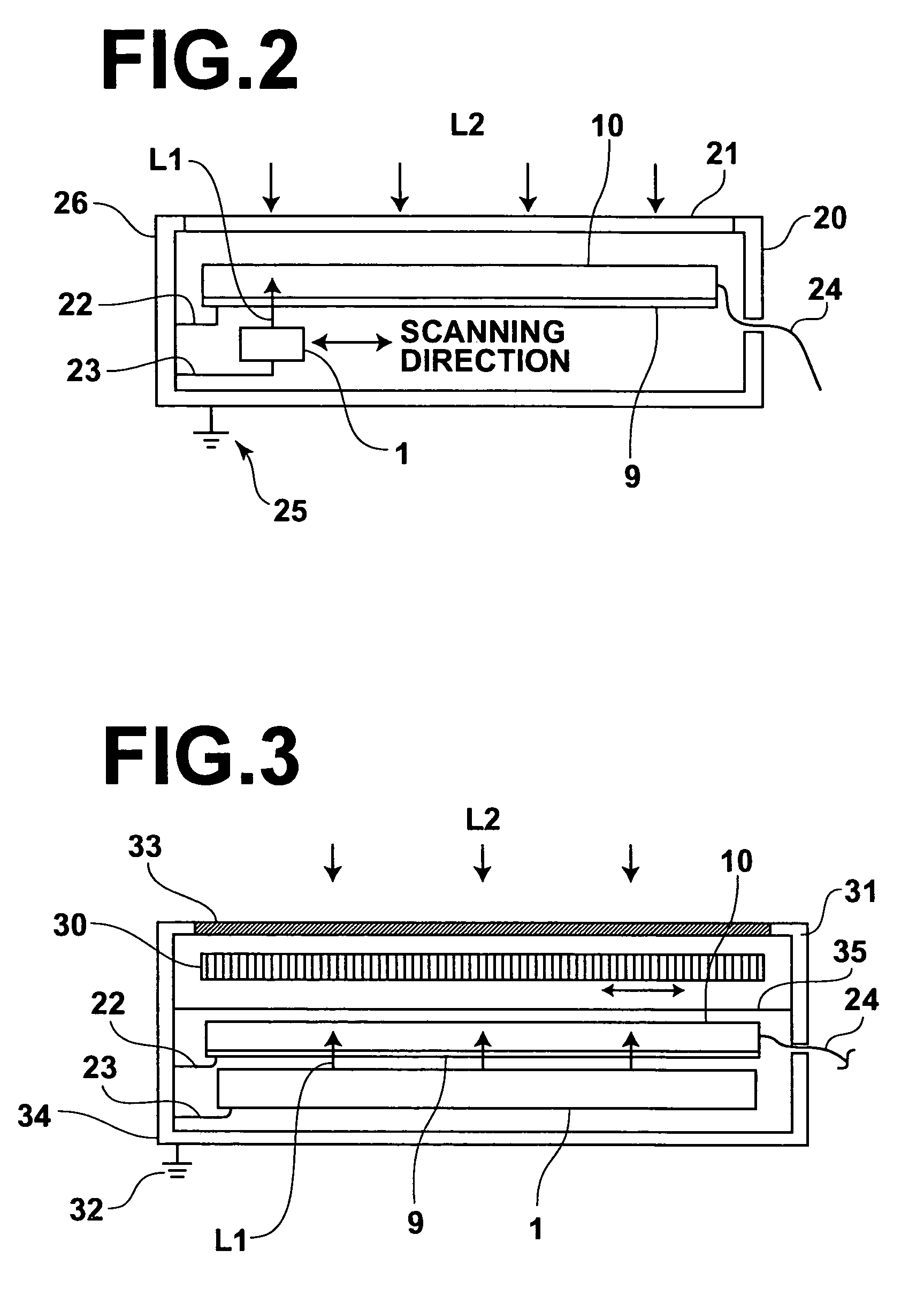
[0070]In the electrostatic latent image read-out apparatus in accordance with the present invention, the reading light source 1 and the electrostatic recording material 10, which are illustrated in FIG. 1A, are located within a casing 20. Also, the casing 20 is grounded. Further, the ITO film 9 of the electrostatic recording material 10 is electrically connected by a wire 22 to the casing 20, and the reading light source 1 is electrically connected by a wire 23 to the casing 20. In this manner, the electrostatic recording material 10, which is provided with the ITO film 9, and the reading light source 1 are grounded. The electrostatic recording material 10 is connected by a flexible print circuit (FPC) 24 to a current detecting section (not shown).
[0071]The casing 20 has an electrostatic shielding box structure formed from an electrical conductor material and is grounded by a grounding conductor 25. A wall 21 of the casing 20, which wall stands facing the incidence side of the recor...
third embodiment
[0076]In the electrostatic latent image read-out apparatus in accordance with the present invention, the reading light source 1, the electrostatic recording material 10, and a moving grid 30 acting as the moving member are located within a casing 31. The reading light source 1 and the electrostatic recording material 10 are grounded. Also, the moving grid 30 is accommodated within an electrostatic shielding box.
[0077]The moving grid 30 is provided with recording light low-absorption members and recording light high-absorption members, which extend in the direction normal to the plane of the sheet of FIG. 3 and are located in a striped pattern. At the time of the irradiation of the recording light L2 to the electrostatic recording material 10, the moving grid 30 is vibrated in the directions indicted by the double headed arrow in FIG. 3.
[0078]The casing 31 has an electrostatic shielding box structure formed from an electrical conductor material and is grounded by a grounding conducto...
PUM
 Abstract
Description
Claims
Application Information
 - R&D
- Intellectual Property
- Life Sciences
- Materials
- Tech Scout
- Unparalleled Data Quality
- Higher Quality Content
- 60% Fewer Hallucinations
Browse by: Latest US Patents, China's latest patents, Technical Efficacy Thesaurus, Application Domain, Technology Topic, Popular Technical Reports.
© 2025 PatSnap. All rights reserved.Legal|Privacy policy|Modern Slavery Act Transparency Statement|Sitemap|About US| Contact US: help@patsnap.com


