Core-shell structure having controlled cavity inside and structure comprising the core-shell structure as component, and method for preparation thereof

a core-shell structure and cavity inside technology, applied in the field of core-shell structure, can solve the problems of difficult control of particle diameter, inability to realize expected results, and inability to realize photocatalysts of high efficiency

Inactive Publication Date: 2008-06-03
JAPAN SCI & TECH CORP
View PDF3 Cites 35 Cited by
  • Summary
  • Abstract
  • Description
  • Claims
  • Application Information

AI Technical Summary

Benefits of technology

[0016]Said core-shell structure is a porous material having near a nanoparticle the optimally adjustable void space inside a shell as the chemical reaction space for specific catalytic reactions, or material syntheses, or as the field for adsorption or enclosing of a specific material. And specific catalytic reactions, or material syntheses, or adsorption or enclosing of a specific material can be conducted highly efficiently and selectively therein.
[0018]Still further, the method of preparation of a core-shell structure having an adjustable void space inside a shell in accordance with the present invention is characterized in that: a particle comprising a photoetchable solid is prepared while its particle diameter is controlled; a particle surface is chemically modified with a chemical material containing a component element capable of bonding to said particle surface and a group containing a component element of non-photoetchable oxide, thereby said group is introduced into said particle surface; a coating film made of said oxide is formed by hydrolyzing said group containing a component element of non-photoetchable oxide; a core-shell structure is formed with said particle as a core, and said coating film as a shell; said core-shell structure is photo-irradiated in a photoetching solution of controlled wavelength; and an adjustable void space is formed inside the core-shell structure. According to this method, a core-shell structure having an adjustable void space inside a shell can be prepared.
[0024]Forming of an adjustable void space inside a core-shell structure by said photo-irradiation with controlled wavelength, the particle diameter is controlled by photoetching with the light of wavelength of absorption edge corresponding to said predetermined particle diameter. By this method, the core of the core-shell structure absorbs the light to be photoetched, and its particle diameter is reduced. With the reduced particle diameter, the wavelength of absorption edge of a core moves to the shorter wavelength side by quantum size effect, and the core becomes non-photoetchable if the wavelength of absorption edge of the core becomes shorter than the wavelength of the irradiated light. By selecting the wavelength of the irradiated light, the particle diameter can be made to the predetermined size. Since the particle diameter can be made to the predetermined size, a core-shell structure having an adjustable void space inside a shell can be prepared.

Problems solved by technology

However, since nanoparticles coagulate by Van der Waals force, the chemical species involved in catalytic reaction cannot be adsorbed on a nanoparticle, thereby an expected result cannot be realized.
That is, a photocatalyst of high efficiency cannot be realized because an adjustable void space does not exist near a nanoparticle.
However, in the nanoparticle-mesoporous material complex prepared by said method, the particle diameter of a nanoparticle differs by the location inside mesoporous material, and therefore it is quite difficult to control particle diameter.
For this reason, it is extremely difficult by the prior art to prepare porous material having the controlled nano void space near a nanoparticle.
In other words, it has been difficult by the prior art to prepare the structure having the controlled nano void space near a nanoparticle, and structures having said structure as a constituent unit.

Method used


Image

  • Core-shell structure having controlled cavity inside and structure comprising the core-shell structure as component, and method for preparation thereof
  • Core-shell structure having controlled cavity inside and structure comprising the core-shell structure as component, and method for preparation thereof
  • Core-shell structure having controlled cavity inside and structure comprising the core-shell structure as component, and method for preparation thereof

Examples


Embodiment Construction

[0040]Hereafter, the embodiment of the present invention will be explained in detail referring to the figures. Here, explanation is made with the same symbols and marks assigned to the practically same parts.

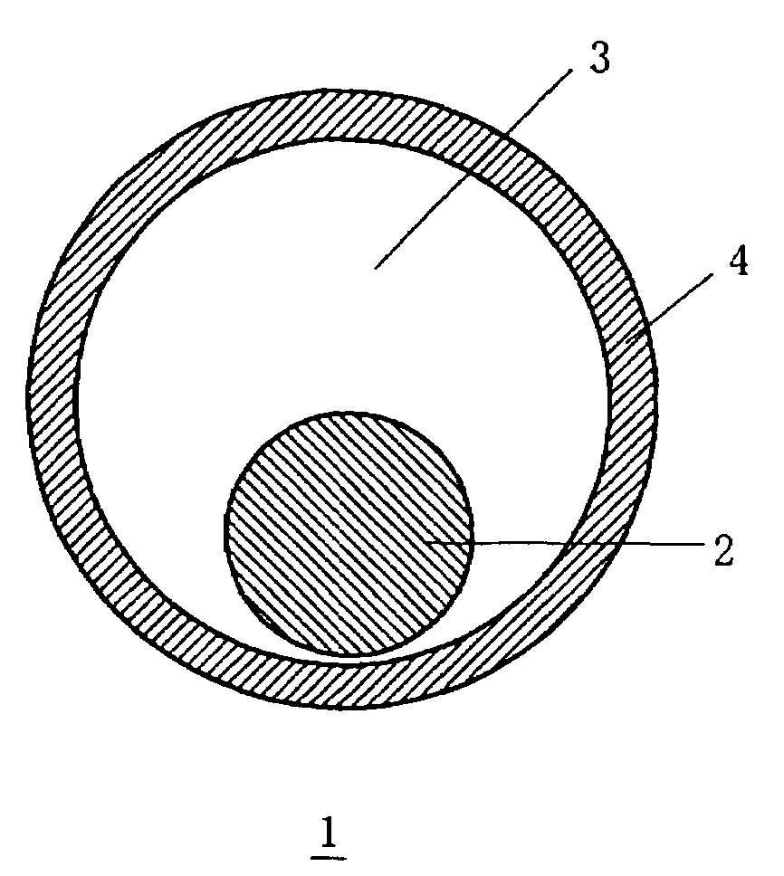
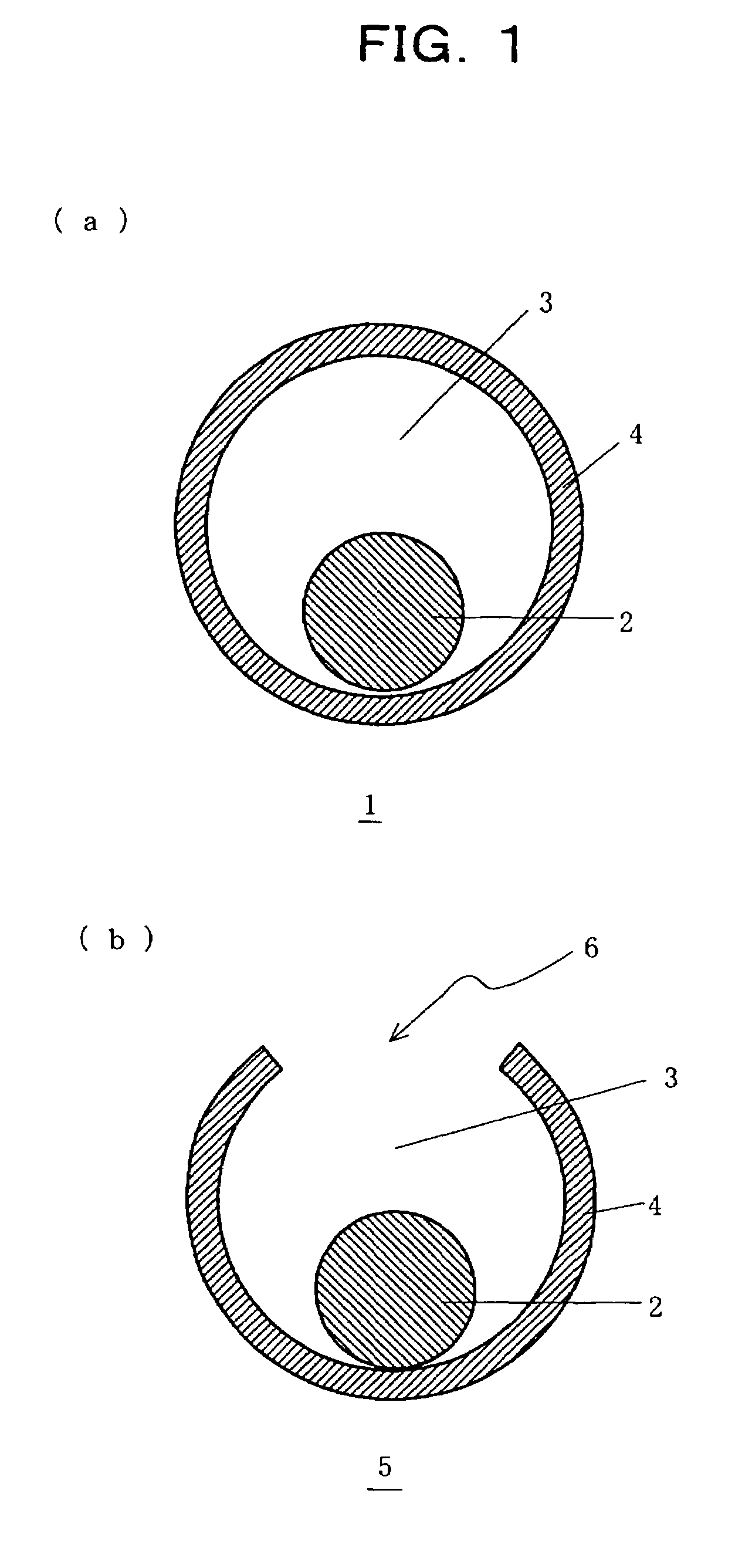
[0041]FIG. 1 is an illustrative cross sectional view showing the structure of a core-shell structure having an adjustable void space inside a shell of the present invention. As shown in FIG. 1(a), a core-shell structure having an adjustable void space inside a shell 1 comprises a core 2 made of a nano fine particle and a shell 4 coating the core 2 via a void space inside a shell 3. The size of the void space inside a shell 3 is controlled to an arbitrary size depending on the field of application. Though not illustrated in the figure, the shell 4 has numerous micropores (holes of about several angstrom diameter).

[0042]FIG. 1(b) shows another embodiment of a core-shell structure having an adjustable void space inside a shell of the present invention, and a core-shell structure 5 ...


PUM

PropertyMeasurementUnit
diameteraaaaaaaaaa
diameteraaaaaaaaaa
diameteraaaaaaaaaa

Abstract

A core-shell structure comprises a core (2) comprising nanoparticles and a shell (4) coating the core (2), and its void space (3) formed by the core (2) and the shell (4) is controlled. A method of preparing the core-shell structure comprises: forming particles comprising a photoetchable semiconductor, metal or polymer and coating the particles with a shell (4) comprising a non-photoetchable semiconductor, metal or polymer, to form a core-shell structure (5); and irradiating the core-shell structure with a light having a controlled wavelength in the photoetching solution to form an adjustable void space inside a shell (3) within the core-shell structure by the size-selective photoetching method. The core-shell structure allows the preparation of a catalyst exhibiting an extremely high efficiency, and can be used as a precursor for preparing a nanomaterial required for a nanodevice.

Description

TECHNICAL FIELD[0001]The present invention relates to a core-shell structure used for catalysts, electron device materials, and the like, and more particularly relates to a core-shell structure having an adjustable void space inside a shell.BACKGROUND ART[0002]Porous materials are widely used for catalysts, adsorbents, surface active agents, and the like. A porous material is a material having micropores of a certain shape, and, among them, a porous material having micropores the diameter of which is 2 nanometer (hereinafter the abbreviated term nm to be used) or less is called a microporous material, and that the diameter of which is 2-50 nm is called a mesoporous material. As a microporous material, for example, zeolite is well known. Zeolite is a crystalline material in which such metal atoms as Si and Al are bonded via oxygen, having micropores of a certain shape, and is used, by utilizing said micropores, for example, as a cracking catalyst to crack heavy oil to gasoline, or as...

Claims


Application Information

Patent Timeline
Patent Type & Authority Patents(United States)
IPC IPC(8): B32B5/16B05D7/00B01J13/02B82B1/00B01J27/04B01J31/02B01J33/00B01J35/00B82B3/00C01G11/02
CPCB01J13/02B01J27/04B01J33/00B01J35/0013B01J35/004B82Y30/00C01B19/007C01G11/02C09C3/12B01J13/025Y10S977/824B01J31/0272C01P2004/03C01P2004/04C01P2004/34C01P2004/64C01P2004/82Y10T428/2991Y10S977/775Y10S977/777
Inventor TORIMOTO, TSUKASAOHTANI, BUNSHOIWASAKI, KENTARO
Owner JAPAN SCI & TECH CORP
Why Eureka
Try Eureka