
Electric double layer capacitor and method of manufacturing same

a double-layer capacitor and capacitor technology, applied in the field can solve the problems of inability to deliver a large current, drawback of poor high-rate performance, and higher manufacturing costs, so as to improve the high-rate performance, increase the capacity of electric double-layer capacitors, and reduce manufacturing costs

Inactive Publication Date: 2008-06-03
SAGA SANYO IND +1
View PDF4 Cites 23 Cited by
  • Summary
  • Abstract
  • Description
  • Claims
  • Application Information

AI Technical Summary

Benefits of technology

The present invention provides an electric double layer capacitor with improved high-rate performance and increased capacity at lower manufacturing costs. This is achieved by using a microwave activation process on fullerene or carbon nanotube to increase the surface area and the specific surface area of the material, which leads to an increase in the capacity of the capacitor. The activation process involves heating the material from the interior using microwaves, which results in the formation of micropores and macropores and increases the surface area without destroying the molecular structure. The carbon material used in the capacitor can be a mixture of fullerene with -60 and -70 carbon atoms per molecule, which further improves the performance and reliability of the capacitor. The method of manufacturing the capacitor involves preparing an electrode with a carbon material and a binder, impregnating an electrolyte solution into the electrode, and using a microwave activation process on the carbon material. The use of microwave activation results in a uniform heating of the material, which leads to improved performance and capacity of the capacitor.

Problems solved by technology

The electric double layer capacitor using the porous carbon material for the polarizable electrodes shows large internal resistance and is therefore unable to deliver a large current; in other words, it has a drawback of poor high-rate performance.
In addition, the porous carbon material needs to be fabricated through complicated manufacturing processes such as an alkali activation process and a steam activation process, necessitating higher manufacturing costs.
Furthermore, the specific surface area of the porous carbon material almost reaches its limit at 3200 m2 / g, and it is difficult to make the specific surface area higher than the limit.
A problem with the foregoing conventional techniques, however, has been that when the fullerene is subjected to an alkali activation process or a steam activation process for a long period of time or the carbon nanotube is subjected to an alkali activation process for a long period of time for the purpose of improving the capacity of the electric double layer capacitor further, molecular structures of the fullerene and the carbon nanotube are destroyed, and thus, further increase in the capacity has not been possible.

Method used


Image

  • Electric double layer capacitor and method of manufacturing same
  • Electric double layer capacitor and method of manufacturing same
  • Electric double layer capacitor and method of manufacturing same

Examples


first preferred embodiment

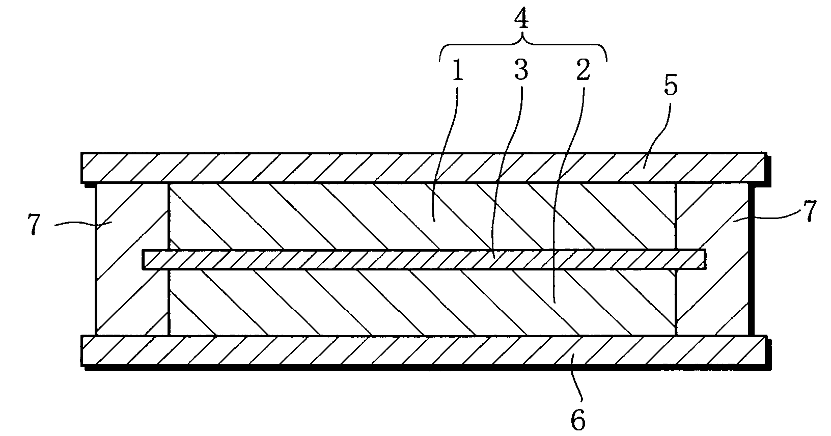
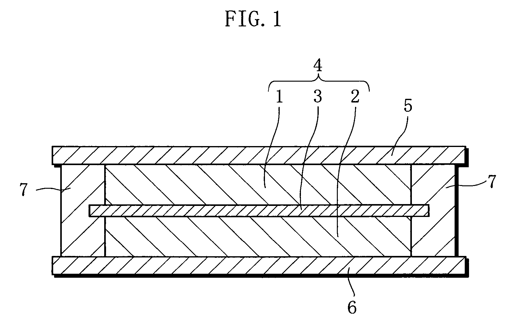
[0041]An electric double layer capacitor according to one embodiment of the present invention has an electrode unit 4, as illustrated in FIG. 1. In the electrode unit 4, a first polarizable electrode (positive electrode) 1 and a second polarizable electrode (negative electrode) 2, both of which contain fullerene that has been activated by microwave heating, are opposed to each other with a separator 3 made of cellulose-based nonwoven fabric interposed therebetween. The electrode unit 4 is accommodated in a space formed by two current collectors 5 and 6, both made of etched aluminum foil, and insulative resin 7. An electrolyte solution is impregnated in the electrode unit 4. The first polarizable electrode 1 and the second polarizable electrode 2 are electrically connected to the current collector 5 and the current collector 6, respectively.

[0042]The thickness of the electric double layer capacitor was 3.2 mm and the diameter thereof was 15.0 mm.

[0043]The above-described electric dou...

second preferred embodiment

[0051]A coin-shaped electric double layer capacitor was fabricated in the same manner as in the first preferred embodiment except that the active material was prepared in the following manner.

[0052]First, an aggregate of carbon nanotube was prepared by a laser application process in which CO2 laser was applied to a graphite target under the conditions set out below. Thereafter, in order to remove the hemispherically shaped portions at end portions of each carbon nanotube to form openings, the carbon nanotubes were treated with a nitric acid solution. Thus, open-end tube-shaped carbon nanotubes were prepared. It should be noted that a carbon nanotube has a structure in which a graphene sheet (in which carbon atoms are arrayed at vertexes of hexagons) is rolled up in a tubular shape. A multilayer structure carbon nanotube is composed of two or more graphene sheets, while a single-layer structure carbon nanotube is composed of a single graphene sheet.[0053]Conditions of CO2 Laser Appli...

example a

[0061]An electric double layer capacitor fabricated according to the first preferred embodiment was employed as Example A.

[0062]The electric double layer capacitor thus fabricated is hereinafter referred to as a capacitor A of the invention.

Comparative Example X1

[0063]Activated carbon and potassium hydroxide were mixed at a weight ratio of 4:1 and stirred at 500° C. for 60 minutes to activate the material. An electric double layer capacitor was fabricated in the same manner as in Example A except that the alkali-activated carbon that was activated by the just-described alkali activation process was used as the carbon material (active material) of the pair of polarizable electrodes.

[0064]The electric double layer capacitor thus fabricated is hereinafter referred to as a comparative capacitor X1.


PUM

PropertyMeasurementUnit
temperatureaaaaaaaaaa
diameteraaaaaaaaaa

Abstract

An electric double layer capacitor and a method of manufacturing are provided that are capable of improving high-rate performance and increasing capacity at lower costs. The electric double layer capacitor includes: an electrode unit having a pair of polarizable electrodes, each composed of a carbon material, and a separator interposed between the pair of polarizable electrodes; and an electrolyte solution impregnated in the pair of polarizable electrodes and the separator. The carbon material of at least one of the pair of polarizable electrodes contains fullerene activated by a microwave activation process and / or carbon nanotube activated by a microwave activation process.

Description

BACKGROUND OF THE INVENTION[0001]1. Field of the Invention[0002]The present invention relates to an electric double layer capacitor that comprises an electrode unit having a pair of polarizable electrodes and a separator interposed between the pair of polarizable electrodes, the pair of polarizable electrodes each containing a carbon material, and in which the pair of polarizable electrodes is impregnated with an electrolyte solution. The invention also relates to a method of manufacturing the capacitor.[0003]2. Description of Related Art[0004]A well-known example of electric double layer capacitor is a coin-shaped electric double layer capacitor having the following configuration. The coin-shaped electric double layer capacitor comprises an element having a pair of polarizable electrodes, each composed mainly of a carbon material, and a porous separator interposed between the pair of polarizable electrodes. The element is accommodated in a case composed of a pair of current collect...

Claims


Application Information

Patent Timeline
Patent Type & Authority Patents(United States)
IPC IPC(8): H01G9/00
CPCB82Y10/00H01G9/058H01G9/155H01G11/36H01G11/34Y10T29/417Y02E60/13H01G11/24H01G11/22
Inventor YOSHIMITSU, SATORU
Owner SAGA SANYO IND
Learn More