Measurement of concentrations and binding energetics

a technology of concentration and energetics, applied in the field of measuring concentrations and binding energetics, can solve the problems of high labor intensity, limited rate at which these parameters are measured by current methodology, and high labor intensity,

Active Publication Date: 2008-06-17
MASSACHUSETTS INST OF TECH
View PDF12 Cites 22 Cited by
  • Summary
  • Abstract
  • Description
  • Claims
  • Application Information

AI Technical Summary

Benefits of technology

[0019]The free-standing microfluidic channels of the present invention offer at least three advantages over conventional approaches. First, detection is label-free and real-time. This eliminates the need for site-specific attachment of reporter molecules. Second, the thermal detection requires a sample volume that may be several orders of magnitude smaller than conventional microcalorimeters. And third, the detectors themselves are microfluidic channels. This allows the detection to be directly integrated with microfluidic systems.

Problems solved by technology

The rate at which these parameters are measured by current methodology, however, is often limited by requirements for large sample volumes and time-consuming modifications of the molecules under investigation.
For example, relative biomolecular concentration is frequently assayed using two-dimensional gel electrophoresis, a procedure that is time-consuming, labor-intensive, and which requires significant technical expertise to obtain quantitative information.
Although the labeling process is straightforward for DNA, the complexity of a protein's structure poses significant challenges to attaching labels to specific sites while preserving the functionality of the protein molecule.
Although approaches such as the quartz crystal microbalance (QCM) and surface plasmon resonance (SPR) can detect label-free binding, they are difficult to miniaturize for protein arrays.
One limitation of existing label-free detectors is that they tend to be significantly less sensitive than fluorescence detection.
The latter are also limited by the difficulty of monitoring a particular species of interest in a reaction environment.
In many cases, yields of the product of interest are too low to be detected within such large volumes.
This makes it difficult to analyze signals from complex reactions unless results from specific analytical measurements are already available.

Method used


Image

  • Measurement of concentrations and binding energetics
  • Measurement of concentrations and binding energetics
  • Measurement of concentrations and binding energetics

Examples


Embodiment Construction

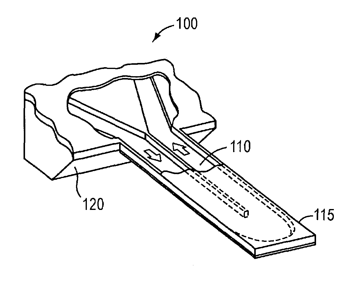
[0032]Refer first to FIG. 1, which illustrates the basic configuration of an analytical cell 100 useful in connection with the present invention. The device 100 includes a U-shaped, free-standing microfluidic channel 110 defined as a hollow within an elongated, finger-like cantilever 115 that projects from (and is integral with or joined to) a mechanically stable supporting substrate 120. Fluid flowing through a channel within the substrate enters the cantilever 115 and traverses the channel 110 as indicated by the arrows.

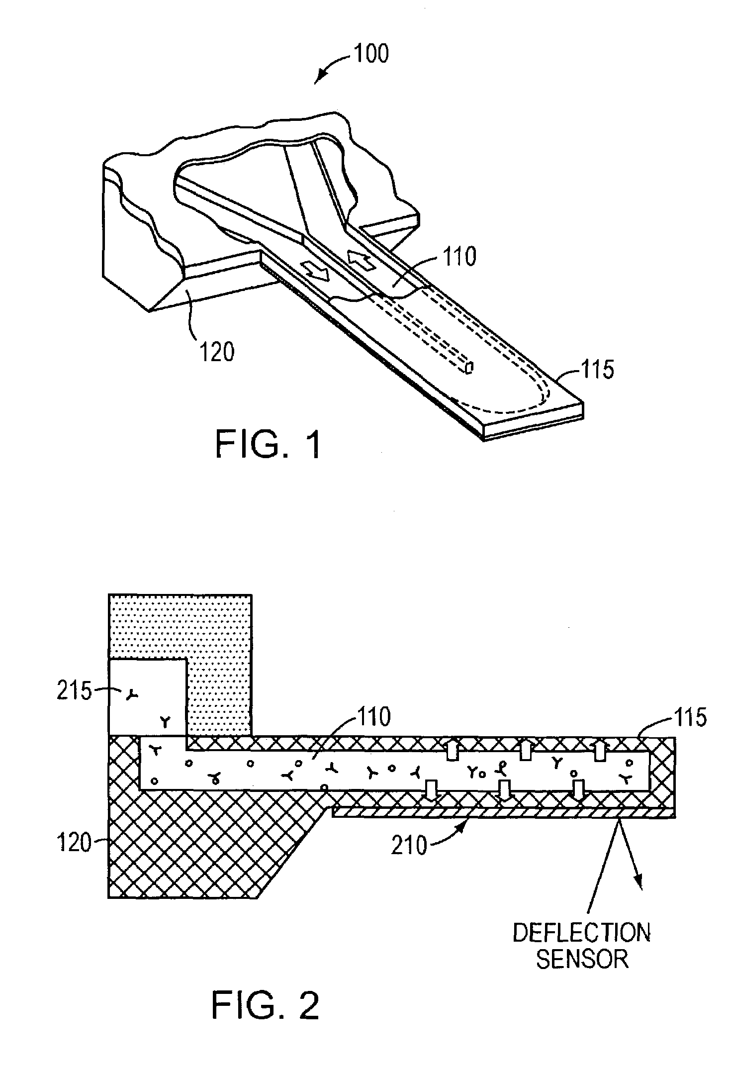
[0033]In one configuration, calorimetric measurements are accomplished by detecting the bending of a thermal bimorph. As shown in FIG. 2, the bimorph comprises the cantilever 115 containing a microfluidic channel 110 and a material (e.g., a metal, such as gold or aluminum) 210 that is deposited on the exterior surface of the cantilever 115. The material 210 has a coefficient of thermal expansion different from that of the cantilever 115. As a result, a temperature ...


PUM

PropertyMeasurementUnit
volumesaaaaaaaaaa
mass resolutionaaaaaaaaaa
volumeaaaaaaaaaa

Abstract

Free-standing microfluidic channels are used to both transport and analyze molecules of interest. In a biochemical context, such molecules may be polypeptides, nucleic acids, or other biomolecules. The free-standing channels provide a real-time readout of concentration without the need for labeling with reporter molecules. The channels can also measure enthalpy values and equilibrium constants by detecting heat released from or absorbed by the sample.

Description

RELATED APPLICATION[0001]This application claims the benefits of and priority to U.S. Provisional Application Ser. No. 60 / 405,184, filed on Aug. 22, 2002, the entire disclosure of which is hereby incorporated by reference.BACKGROUND OF THE INVENTION[0002]1. Field of the Invention[0003]The present invention relates to measuring analyte concentrations and the affinity and energetics of chemical binding.[0004]2. Background Information[0005]Analytical study of molecular interactions requires the ability to observe changing molecular concentrations in an environment of interest, and also the ability to quantify chemical kinetics and affinity energetics. This is particularly true in biological contexts, where processes at the cellular and even organismic level often can be traced to changing concentrations and / or binding energetics of biomolecules and cofactors. For example, proteins and their byproducts play a critical role in nearly every event that take place within living cells. The a...

Claims


Application Information

Patent Timeline
Patent Type & Authority Patents(United States)
IPC IPC(8): C12M1/34C12M1/00G01N21/00G01N25/00G01N33/53G01N33/543
CPCG01N33/54366
Inventor MANALIS, SCOTT
Owner MASSACHUSETTS INST OF TECH
Why Eureka
Try Eureka