
Method and apparatus for a pulse width modulated DC-DC converter

a dc-dc converter and pulse width technology, applied in the field of integrated circuits, can solve the problems of increasing the power consumption of dc-dc converters, increasing the complexity of dc-dc converters, so as to improve the convergence efficiency of pwm signals and a wider range of applicability

Active Publication Date: 2008-06-17
WINBOND ELECTRONICS CORP
View PDF7 Cites 16 Cited by
  • Summary
  • Abstract
  • Description
  • Claims
  • Application Information

AI Technical Summary

Benefits of technology

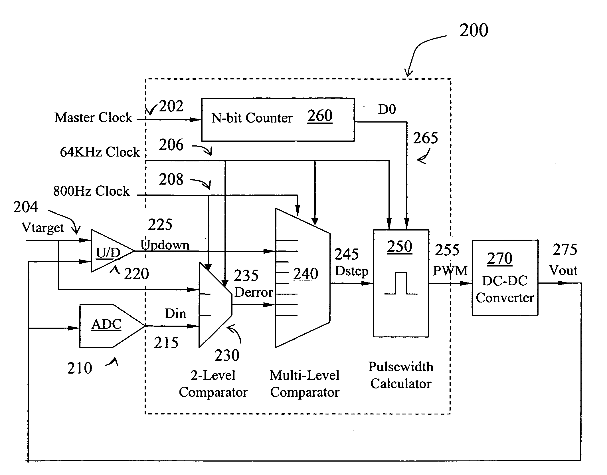
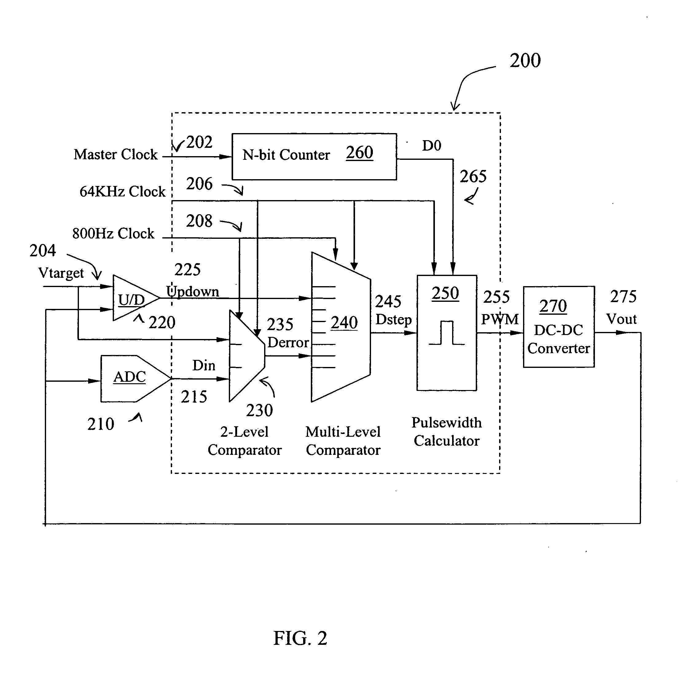
The present invention provides techniques for controlling a DC-DC converter used to supply power to various electronics and telephony devices. The invention includes methods for generating a pulse width modulation (PWM) signal using multiple clock pulses and adjusting the duty cycle of the PWM signal based on feedback measurements. The invention also includes apparatus for controlling the output voltage of a DC-DC converter and a DC-DC converter including a feedback control circuit and a feedback control signal. The technical effects of the invention include improved convergence efficiency of PWM signals, improved fine tuning of PWM signals, and improved control of output voltage in DC-DC converters.

Problems solved by technology

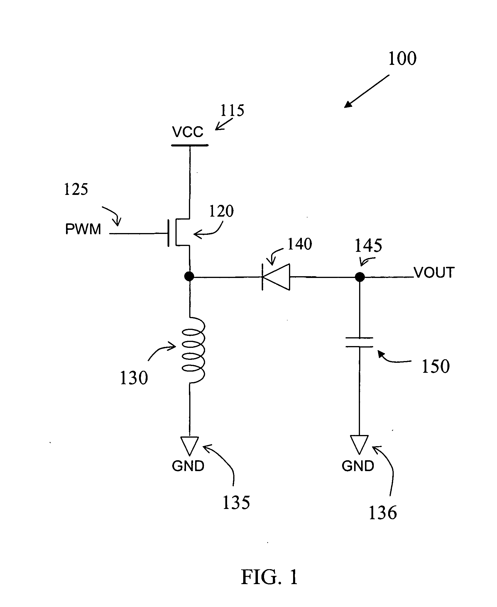
Unfortunately, conventional analog PWM controlled DC-DC converters suffer from certain limitations.
For instance, conventional analog PWM controlled DC-DC converters can be susceptible to temperature and process variation and often consume more power and larger silicon area.
There may also be other limitations with these conventional analog PWM controlled DC-DC converter.
Although successful, conventional digital PWM converters suffer from certain drawbacks.
Conventional DC-DC converters utilizing digital PWMs tend to suffer from limited accuracy, because adjustment time step is limited by clock rate and incremental voltage change is dictated by digitization limitations.
Further, conventional digital PWM converters tend to have relatively long response time, causing noise and output voltage overshoot or undershoot.

Method used


Image

  • Method and apparatus for a pulse width modulated DC-DC converter
  • Method and apparatus for a pulse width modulated DC-DC converter
  • Method and apparatus for a pulse width modulated DC-DC converter

Examples


Embodiment Construction

[0020]According to the present invention, techniques directed to integrated circuits are provides. More particularly, the invention provides a method and apparatus for controlling a DC-DC converter used to supply power to various electronics and telephony devices. Merely by way of example, the invention provides techniques for generating a pulse width modulation (PWM) signal in a DC-DC converter and adjusting its duty cycle using multiple thresholds according to at least two separate schedules, namely a coarse tuning cycle and a fine tuning cycle. But it would be recognized that the invention has a much broader range of applicability. For example, the invention can be applied to improve convergence efficiency of PWM signals in other applications.

[0021]A method according to an embodiment of this invention includes at least two major parts: for example, one for coarse tuning and one for fine tuning. In the coarse tuning process, DC-DC converter output voltage is periodically sampled a...


PUM


Abstract

A pulse width modulated pulse signal is generated and its duty cycle adjusted according to at least two different schedules, for example, a coarse tuning cycle and a fine tuning cycle. The target duty cycle is derived according to an offset between output voltage and target voltage, as well as the rate of changes in the offset. In the coarse tuning cycle, large changes in the control signal pulse width is used to drive output voltage to target at a fast pace. As output voltage approaches target voltage, smaller adjustment are made to the duty cycle of the control pulse width in the fine tuning cycle. The rate of pulse width change is also taken into consideration, to further improve operation of the DC-DC converter.

Description

BACKGROUND OF THE INVENTION[0001]The present invention is directed to integrated circuits. More particularly, the invention provides a method and apparatus for controlling a DC-DC converter used to supply power to various electronics and telephony devices. Merely by way of example, the invention provides techniques for generating a pulse width modulation (PWM) signal in a DC-DC converter and adjusting its duty cycle using multiple thresholds according to at least two separate schedules, namely a coarse tuning cycle and a fine tuning cycle. But it would be recognized that the invention has a much broader range of applicability. For example, the invention can be used to improve convergence efficiency of PWM signals in other applications.[0002]DC to DC converters are often found in electronic devices. These devices include cellular phones and laptop computers which may require certain voltage levels different than supplied by the power source, or even negative voltages. In telephony ap...

Claims


Application Information

Patent Timeline
Patent Type & Authority Patents(United States)
IPC IPC(8): H02M1/08
CPCH02M3/157
Inventor DUAN, ZHAN
Owner WINBOND ELECTRONICS CORP
Learn More