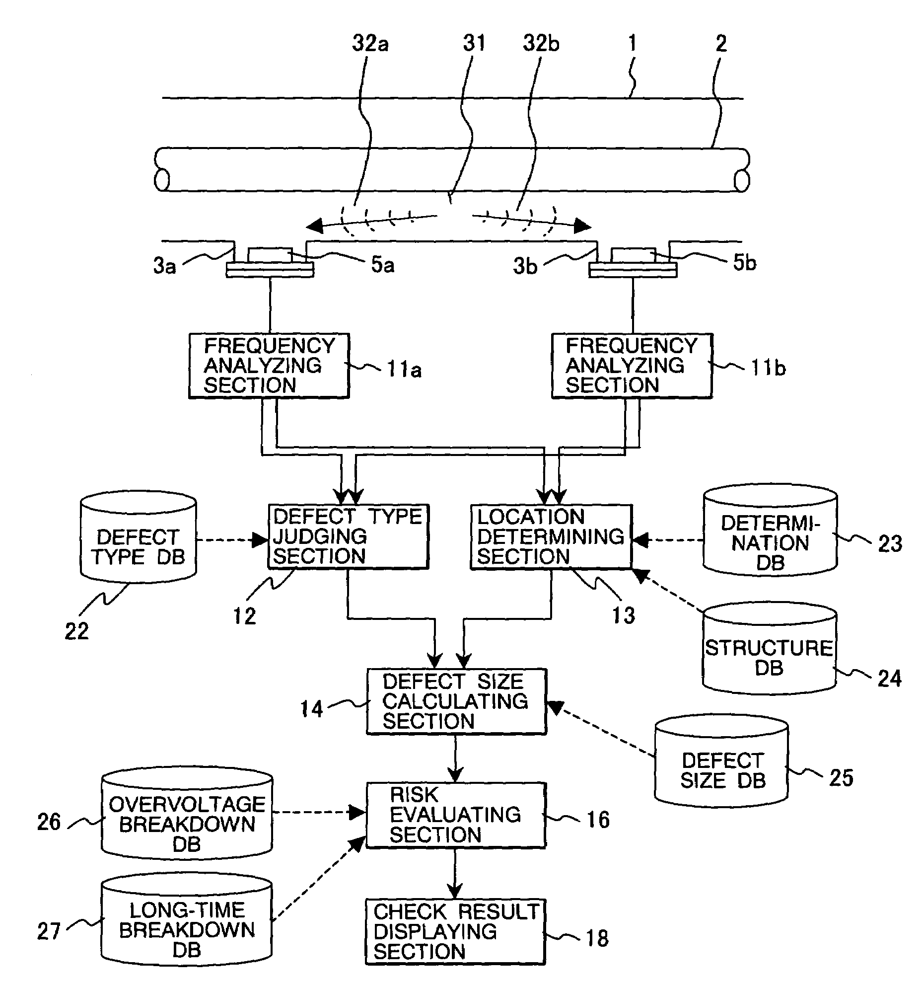
Method and system for monitoring partial discharge in gas-insulated apparatus
a gas-insulated apparatus and partial discharge technology, applied in the direction of fault location, fault location by conductor type, instruments, etc., can solve the problems of dielectric breakdown in the end, drastically degraded insulation characteristic in a non-uniform field, etc., and achieve the effect of drastically reducing maintenance costs
- Summary
- Abstract
- Description
- Claims
- Application Information
AI Technical Summary
Benefits of technology
Problems solved by technology
Method used
Image
Examples
embodiment 1
[0065]FIG. 30 shows a construction of a gas-insulated switching apparatus to which the present invention applies, showing a system configuration capable of continuous monitoring. The gas-insulated switching apparatus is a metallic container with ground potential, which contains a circuit breaker 55, disconnecting switch 54, grounding switch 53, bus 57, arrestor 58, current transformer 52, and transformer 56, and is filled with SF6 gas having excellent insulation performance and current limiting performance.
[0066]Power is led into the apparatus from an overhead wire or power cable via a bushing 51 or cable head, and supplied to the bus 57, disconnecting switch 54 and circuit breaker 55. The arrestor 58 for controlling overvoltage due to lightning is installed near the bushing for incoming power, and the transformer 56 for measuring the voltage and current transformer 52 for measuring the current are installed at appropriate positions.
[0067]Since existence of any insulation failure in...
embodiment 2
[0122]A case where the defect type is protrusion has been described in Embodiment 1. Next, another defect size calculation in case of different defect type is described hereunder.
[0123]Typical defect type in a gas-insulated apparatus is defect caught on spacer surface. This is a case where some mixed metallic particle is caught on the spacer for supporting the center conductor in FIG. 30.
[0124]FIG. 32 shows an example particle caught on the surface of the spacer. In case a particle 31 is caught on the surface of the spacer 6, the electromagnetic wave of the caused partial discharge 71 is sensed by the sensor installed inside the gas-insulated apparatus. As shown there, partial discharge 71 is caused at the end of the particle 31 on the surface of the spacer 6.
[0125]The partial discharge 71 caused progresses along the spacer surface. That is to say, in evaluating the signal intensity (discharge level) of the partial discharge 71 from the foreign substance 31 caught on the spacer surf...
embodiment 3
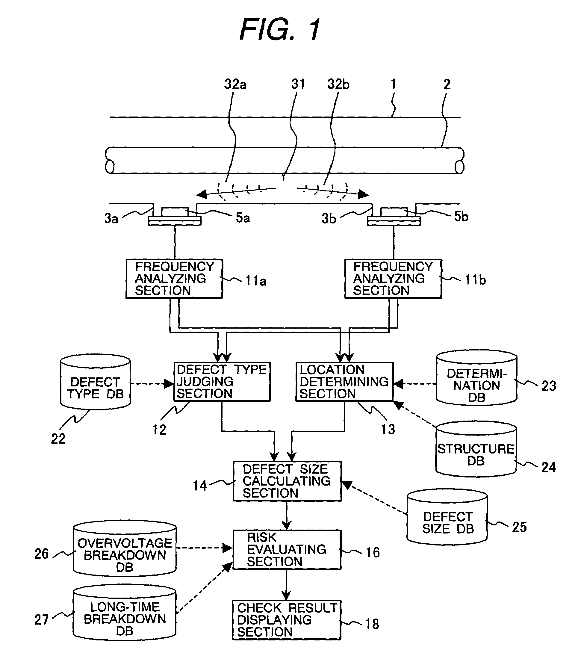
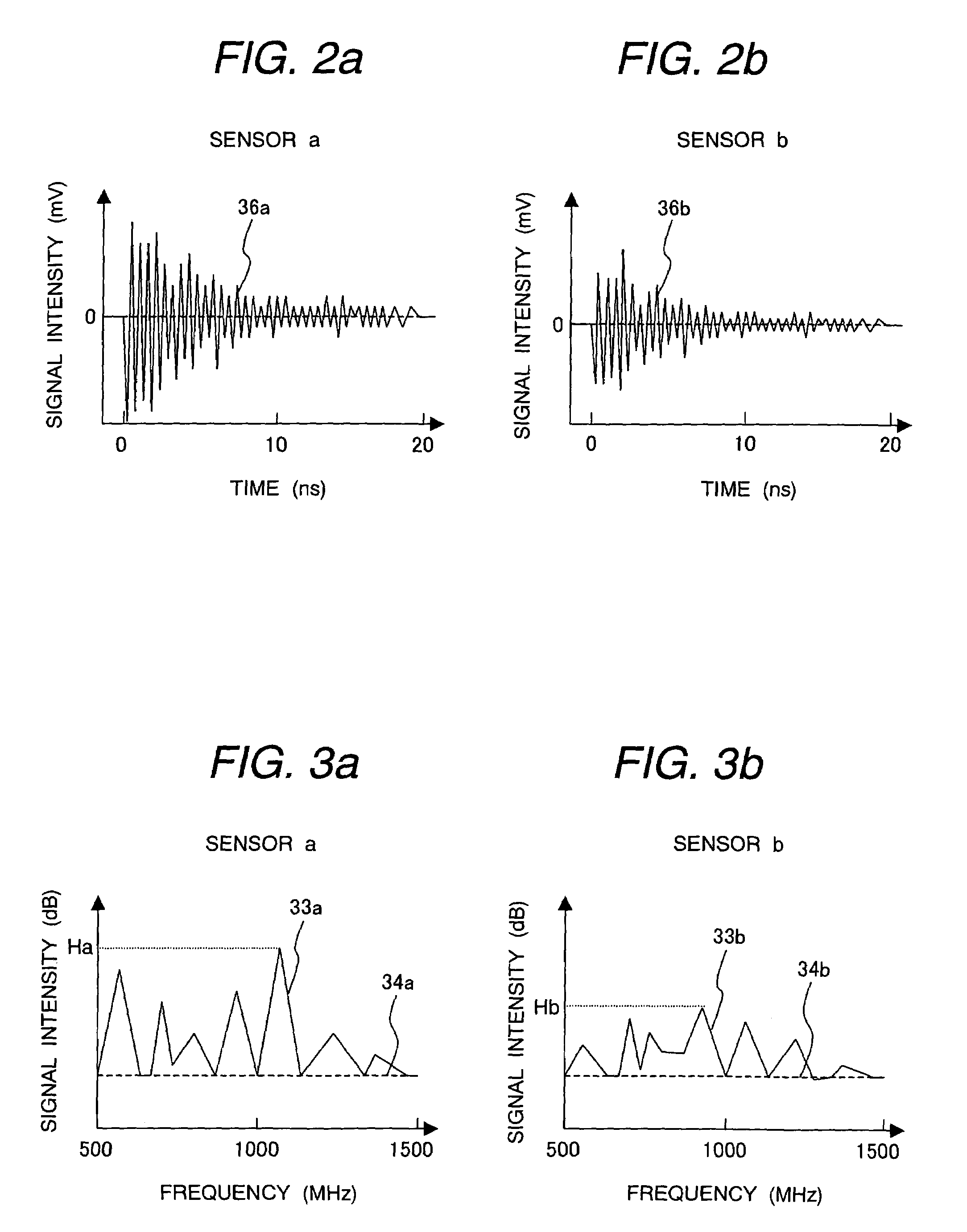
[0130]In estimating the defect size in Embodiment 1 and Embodiment 2, the frequency of the sensed signal is analyzed to obtain the maximum signal intensity (FIG. 3) in the frequency band from 500 MHz to 1500 MHz and the actual discharge intensity is calculated from it. This, however, does not consider the frequency sensed in the frequency band from 500 MHz to 1500 MHz. Since the rising time of partial discharge is very sharp such as in ns (nanosecond) as explained previously, it contains signal components reaching the high-frequency band.
[0131]FIG. 25 shows the frequency characteristic of partial discharge signal. The frequency characteristic in 500 MHz to 1500 MHz exhibits higher signal intensity at lower frequency. This curve can be expressed by Formula (4) in terms of the frequency f, (where C is a constant).
y=−20×log(f)+C (4)
[0132]In other words, same discharge results in different signal intensity depending upon the frequency band and, therefore, the frequency to be sensed mus...
PUM
 Abstract
Description
Claims
Application Information
 - R&D
- Intellectual Property
- Life Sciences
- Materials
- Tech Scout
- Unparalleled Data Quality
- Higher Quality Content
- 60% Fewer Hallucinations
Browse by: Latest US Patents, China's latest patents, Technical Efficacy Thesaurus, Application Domain, Technology Topic, Popular Technical Reports.
© 2025 PatSnap. All rights reserved.Legal|Privacy policy|Modern Slavery Act Transparency Statement|Sitemap|About US| Contact US: help@patsnap.com


