Shift registers free of timing race boundary scan registers with two-phase clock control

a technology of boundary scan register and shift register, which is applied in the field of data registers, can solve the problems of boundary scan register, incongruent delay, and high cost of test equipment, and achieve the effect of avoiding incongruent delay, avoiding incongruent delay, and avoiding inconvenient operation

Active Publication Date: 2008-06-17
GSI TECH
View PDF11 Cites 26 Cited by
  • Summary
  • Abstract
  • Description
  • Claims
  • Application Information

AI Technical Summary

Problems solved by technology

These high density devices pose unique manufacturing challenges, such as the accessibility of test points and the high cost of test equipment.
Due to physical constraints of the printed circuit board, a boundary scan device, and its boundary scan registers, can not always be located as close to the pin under test as is optimal.
Further, the circuit path length from the pin under test to each boundary scan register varies in length, which results in delay.
Other factors also contribute to incongruent delay, such as temperature.
However, in practice the order of data transmission does not track with the clock distribution path.
Accounting for such delays though, across all temperature and process variations, is difficult and burdensome.
However, under normal configurations and operating conditions, significant delays are introduced whereby data racing problems occur.
This results in a data timing race problem.
Racing problems occur because the clock distribution path is usually not tracking with the data transmitting path.
This problem cannot be resolved even when the system cycle time TCK is relaxed.
However, it is difficult to match the transistor delay to the metal wire RC delay in all process corners, power supply levels and temperatures.
Matching these delays significantly increases the overhead.

Method used


Image

  • Shift registers free of timing race boundary scan registers with two-phase clock control
  • Shift registers free of timing race boundary scan registers with two-phase clock control
  • Shift registers free of timing race boundary scan registers with two-phase clock control

Examples


Embodiment Construction

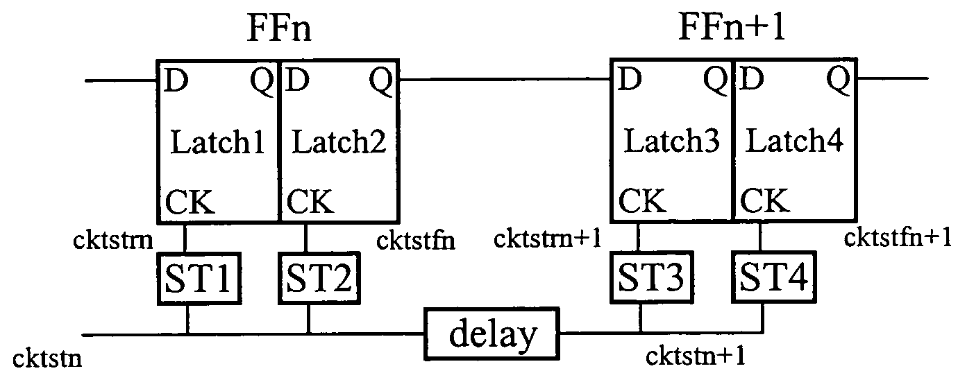
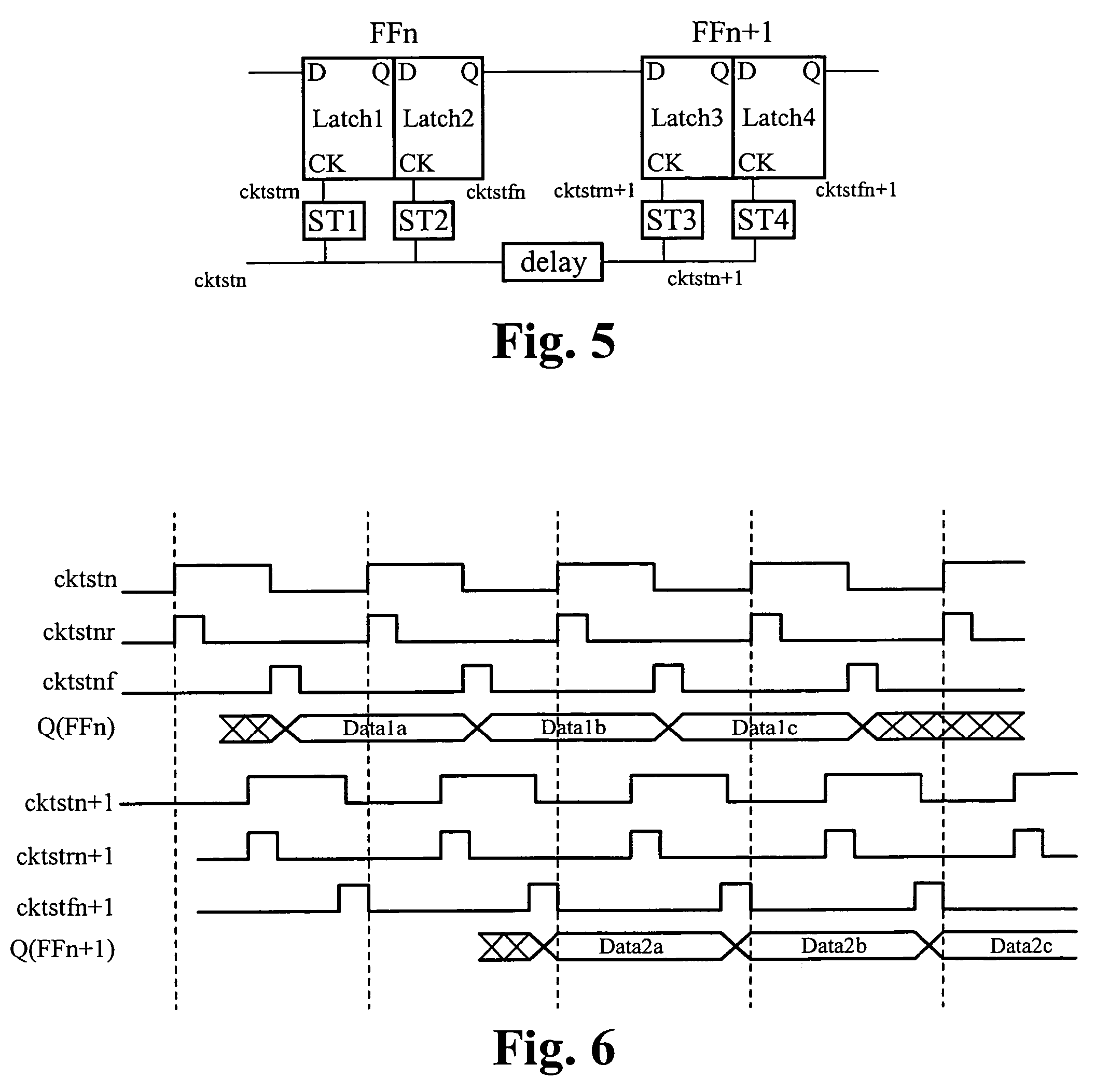
[0030]FIG. 5 illustrates a chain of two boundary scan registers configured according to the two-phase clock signal. A first boundary scan register FFn includes a latch 1 and a latch 2. A second boundary scan register FFn+1 includes a latch 3 and a latch 4. Each latch receives data at the input D, outputs data at the output Q, and receives a clock signal at the clock input CK. A self-timed pulse generator is coupled to the clock input of each latch. As shown in FIG. 5, a self-timed pulse generator ST1 is coupled to the clock input of the latch 1. A self-timed clock pulse generator ST2 is coupled to the clock input of the latch 2. A self-timed pulse generator ST3 is coupled to the clock input of the latch 3. A self-timed pulse generator ST4 is coupled to the clock input of the latch 4. The delay box shown in the clock input signal path represents the inherent delay associated with any physical signal path. The clock signal cktstn is the system clock signal TCK plus any delay associate...


PUM


Abstract

A chain of boundary scan registers is configured to use a two-phase clock signal to avoid data timing race conditions. The two-phase clock signal is generated according to a two-phase clock generator, which includes two self-timed clock pulse generators for each boundary scan register. The two-phase clock generator locally generates a self-timed clock pulse at the rising edge of a clock signal, which triggers a first stage of the boundary scan register. The two-phase clock generator also generates a self-timed clock pulse at the falling edge of the input clock signal, which triggers a second stage of the boundary scan register. The two-phase clock controlled boundary scan register includes two latches, each latch is triggered by one of the self-timed clock pulse generated locally from the rising and falling edge of the input clock signal.

Description

RELATED APPLICATIONS[0001]This application claims priority of U.S. provisional application Ser. No. 60 / 731,394, filed Oct. 28, 2005, and entitled “SHIFT REGISTERS FREE OF TIMING RACE BOUNDARY SCAN REGISTERS WITH TWO-PHASE CLOCK CONTROL”, by the same inventors. This application incorporates U.S. provisional application, Ser. No. 60 / 731,394, filed Oct. 28, 2005, and entitled “SHIFT REGISTERS FREE OF TIMING RACE BOUNDARY SCAN REGISTERS WITH TWO-PHASE CLOCK CONTROL”, in its entirety by reference.FIELD OF THE INVENTION[0002]The present invention relates to the field of data registers. More particularly, the present invention relates to the field boundary scan registers configured to eliminate data racing conditions.BACKGROUND OF THE INVENTION[0003]Historically, most printed circuit board (PCB) testing was done using in-circuit test equipment. Recent advances with VLSI technology now enable microprocessors and Application Specific Integrated Circuits (ASICs) to be packaged into fine pitch...

Claims


Application Information

Patent Timeline
Patent Type & Authority Patents(United States)
IPC IPC(8): G01R31/28
CPCG01R31/318541
Inventor CHEN, HSIN-LEY SUZANNECHUANG, PATRICK T.HUANG, MICHELLE
Owner GSI TECH
Why Eureka
Try Eureka