Processing of shipboard wastewater

a technology for processing wastewater and marine vessels, applied in vessel construction, vacuum distillation separation, separation processes, etc., can solve the problems of high fouling rate and achieve the effect of enhancing subsequent flashing

Inactive Publication Date: 2008-06-24
NAVY SEC OF THE THE UNITED STATES OF AMERICA AS REPRESENTED BY THE
View PDF20 Cites 7 Cited by
  • Summary
  • Abstract
  • Description
  • Claims
  • Application Information

AI Technical Summary

Benefits of technology

[0005]In accordance with the present invention, wastewater is processed in a flash chamber under vacuum established within an upper section thereof by a vacuum pump. Before delivery to the flash chamber, the wastewater is preheated in a heat exchanger to enhance subsequent flashing thereof effected by entry through an orifice. In the flash chamber the wastewater is converted to a water vapor portion in a single evaporation stage, and also into a contaminate portion having oil droplets. Water vapor produced by such flashing rises into and fills the upper chamber section, while liquid waste oil droplets are deposited into a bottom section of the flash chamber. A de-mister filters out contaminants from the rising water vapor entering the upper section of the flash chamber and liquefied water vapor is collected therebelow during removal of such rising water vapor from the flash chamber in a superheated or saturated condition for condensation by cooling. The water condensate and the waste oil are respectively withdrawn by distillate and drain pumps under aut

Problems solved by technology

Such processing systems rely on fine-sized membrane pores which create high fouling rate problems so as to require u

Method used


Image

  • Processing of shipboard wastewater
  • Processing of shipboard wastewater

Examples


Embodiment Construction

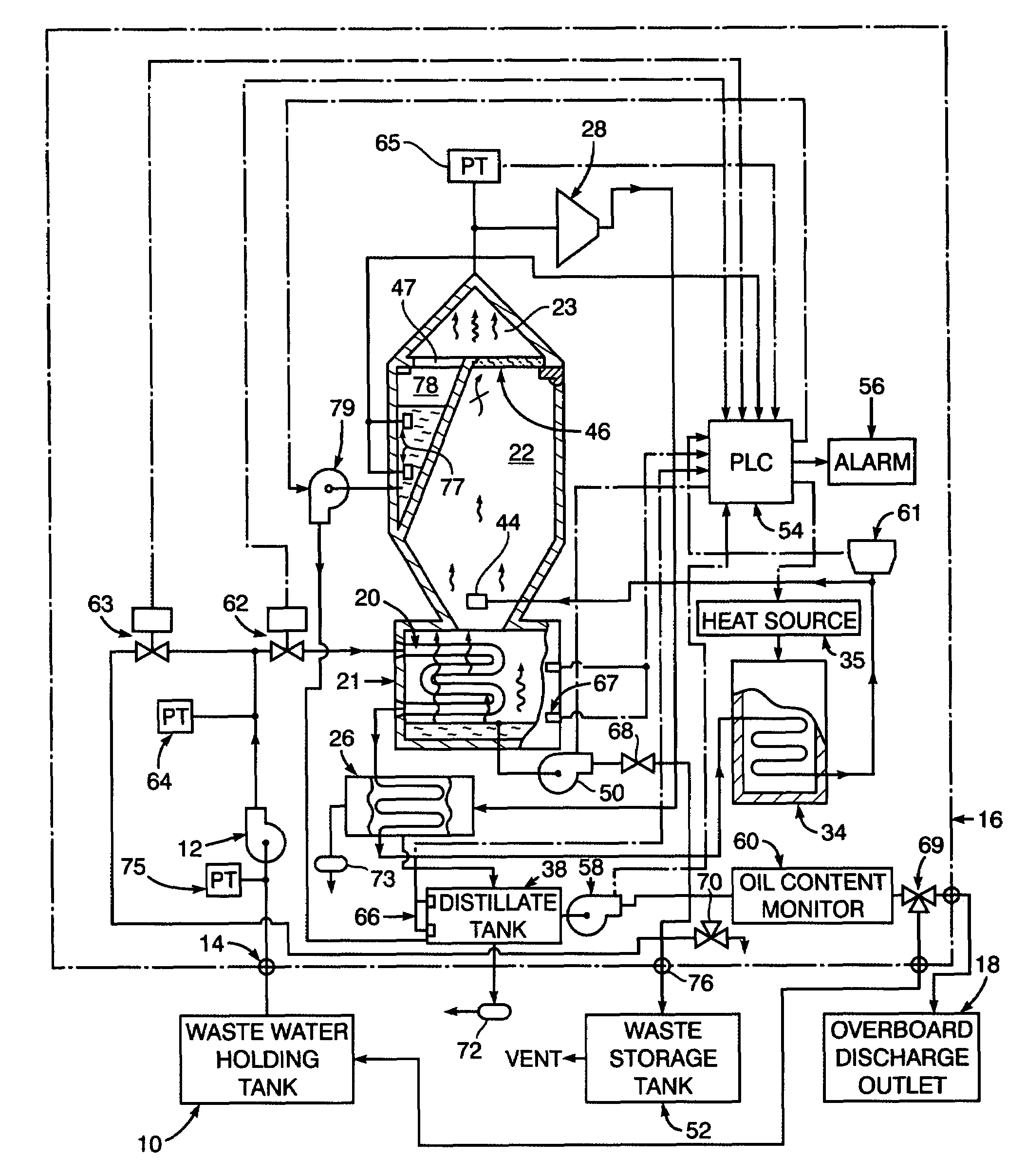
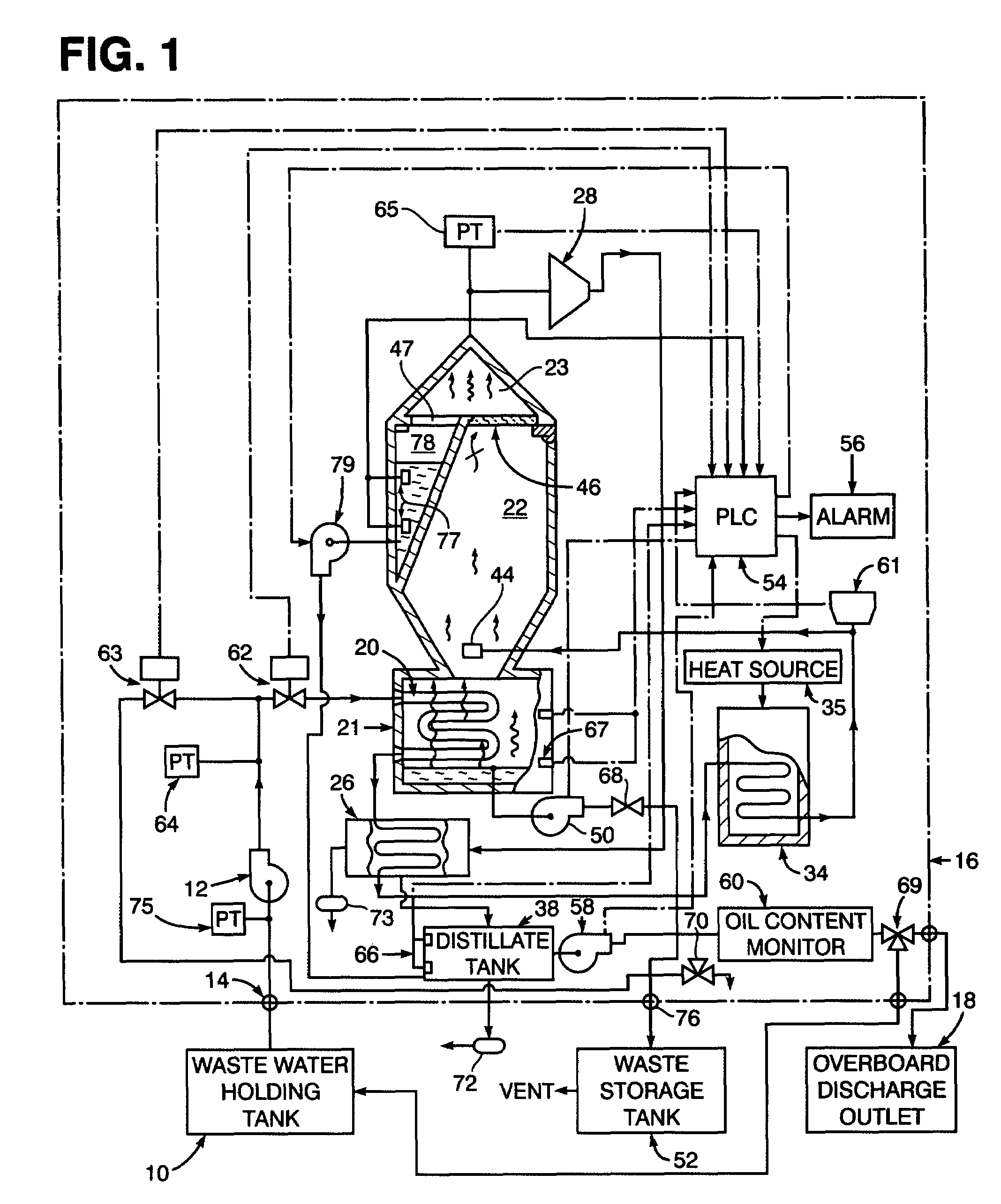
[0009]Referring now to the drawing FIG. 1 in detail, it diagrams a shipboard system for processing wastewater such as bilgewater or graywater received from a source such as a wastewater holding tank 10. According to the embodiment illustrated, the wastewater from the holding tank 10 is initially received through an inlet 14 into an inflow pump 12 for pressurization within a processor, generally referred to by reference numeral 16, from which an oil-free or contaminant free water condensate is obtained for overboard discharge through an outlet 18.

[0010]The wastewater from holding tank 10 after pressurization by pump 12 passes through a heat absorbing coil 20 located within a bottom section 21 of a flash chamber 22 in the processor 16. Heat from water vapor in the bottom section 21 is absorbed by the wastewater within the coil 20 before it is supplied to a condenser 26. The water vapor rising from the bottom section 21 when reaching an upper chamber section 23 of the flash chamber 22 ...


PUM


Abstract

Incoming wastewater is preheated in a heat exchanger before delivery to a flash chamber through an orifice for flashing into water vapor rising into an upper section of the flash chamber which also has a bottom section into which liquid waste oil or other contaminants settles. Rise of such water vapor into the upper chamber section is induced by a vacuum established therein by a vacuum pump withdrawing the water vapor in a superheated and compressed condition for cooling within a condenser from which the incoming wastewater is delivered to a heat exchanger for preheating. The water vapor during rise into the upper section of the flash chamber is filtered to extract contaminates therefrom while liquefied water vapor thereafter formed therein is collected before the remaining water vapor is cooled into the condensate for collection within a distillate tank from which it is withdrawn for overboard discharge after being monitored for oil content. The waste oil and other contaminants in the flash chamber are also withdrawn for separate collection and storage. Such collections of the condensate extracted from the water vapor, the liquefied water vapor and the waste oil and other contaminants are effected by pumps driven under automatic control.

Description

CROSS-REFERENCE TO RELATED APPLICATION[0001]This application is a division of application Ser. No. 09 / 726,028, filed Nov. 30, 2000, now U.S. Pat. No. 6,740,205, entitled, “Processing of Shipboard Wastewater.”STATEMENT OF GOVERNMENT APPLICATION[0002]The invention described herein may be manufactured and used by or for the Government of the United States of America for governmental purposes without the payment of any royalties thereon or therefore.SUBSTITUTE SPECIFICATION[0003]The present invention relates generally to a method for processing of wastewater onboard a marine vessel, involving flashing of the wastewater into water vapor.[0004]Presently, liquid waste in the form of bilgewater is cleansed by processing systems which utilize ultrafiltration membranes to separate oil and water, as disclosed for example in U.S. Pat. Nos. 3,730,848 and 5,932,091 to Kowalski and Tompkins et al. Such processing systems rely on fine-sized membrane pores which create high fouling rate problems so ...

Claims


Application Information

Patent Timeline
IPC IPC(8): B01D3/06B01D1/00B01D3/10B01D3/42C02F1/04
CPCB01D3/06B01D3/10B01D3/42C02F1/048Y10S203/11Y10S159/16Y10S203/08
Inventor MOLINTAS, HENRY J.
Owner NAVY SEC OF THE THE UNITED STATES OF AMERICA AS REPRESENTED BY THE
Why Eureka
Try Eureka