Multi-functional and configurable assay

a multi-functional, configurable technology, applied in the field of multi-functional and configurable assays, can solve the problems of limited application of test strip format assays to semi-quantative or qualitative assays, less accurate, less precise, and less sensitive to analyte presence, etc., to achieve efficient conservation and isolation of analyte, rapid analysis, and simple and accurate results

Inactive Publication Date: 2008-06-24
WAVESENSE INC
View PDF30 Cites 10 Cited by
  • Summary
  • Abstract
  • Description
  • Claims
  • Application Information

AI Technical Summary

Benefits of technology

[0021]The present invention specifically addresses and alleviates to the above-identified deficiencies in the art. In this regard, the present invention pertains to several novel bioassay methodologies, chromatographic devices, and an optional multimode photometer / analyzer which together can perform bioassays with accuracy and precision like that of conventional laboratory formats while retaining the operational simplicity, rapid analysis, and cost-effectiveness like that of test strip formats. The chromatographic devices and novel bioassay methodologies of the present invention further minimize problems associated with the manufacture of test strips which incorporate preapplied capture lines and further, can enable an analyte to be detected in a fluid sample in a manner that efficiently conserves and isolates the analyte present in such sample. Moreover, multimode photometers, novel test strip devices, and unique chemical analysis methods of the present invention represent a versatile, cost effective, simple, and accurate system which can quantify the amount of a chemical substance present in a sample that has not heretofore been available via prior art bioassay test strips.
[0022]According to a first aspect of the present invention, there is provided a novel magnetic chromatography method which consists of the steps of contacting activated magnetic particles suspended in a reaction mixture with a chromatographic medium (e.g., test strip or chromatographic plate), and thereafter applying a magnetic field thereto. As the activated magnetic particles flow laterally within the plane of the medium they encounter the applied magnetic field. The applied magnetic field attracts the magnetic particles forming a magnetic barrier that selectively retains magnetic particles while allowing the reaction mixture to continue to flow laterally thereacross. In an embodiment particularly useful in performing cell capture assays, the reaction mixture with magnetic particles is contacted upon an intermediate portion of a chromatographic medium having a magnetic field applied at the point of contact. The reaction mixture is thus caused to flow bilaterally across the medium, with the magnetic particles having the analyte of interest complexed therewith being captured at the starting point, or point of sample introduction, thus conserving the amount of analyte in the reaction mixture that would otherwise become lost through reaction mixture flow.
[0023]As such, there is thus eliminated the conventional capture lines formed by bound receptors that are utilized in prior art immunoassays as well as analyte loss that can occur during the assay. In this regard, a capture line is in effect assembled during the assay, and preferably at the outset. Advantageously, the magnetic chromatography assay methods of the present invention allow test strips and the like to be manufactured without preapplied capture lines. However, the methods of the present invention also anticipate a magnetic chromatography test strip having both preapplied capture lines and capture lines formed during the bioassay using magnetic chromatography as may be desired for a specific application.

Problems solved by technology

As a consequence, the high cost and complexity of operation associated with such formats limits widespread utilization thereof.
Additionally, such test strip assays may be utilized by unskilled laborers and can produce results on-site (i.e., outside a laboratory facility).
Unfortunately, despite their cost-effectiveness and simplicity of use, typical test strip format assays are less accurate, less precise, and less sensitive to analyte presence than conventional formats.
As a result of such drawbacks, the application of test strip format assays has been limited to semi-quantitative or qualitative assays.
Of further significant disadvantage is the fact that virtually all test strip format assays are formed to have a sequential, generally-linear configuration so as to facilitate the necessary lateral flow thereacross.
As such, a substantial portion of the target analyte sought to be detected can and frequently is missed altogether which can adversely affect the quantitative and qualitative results generated by such assays.
Such potential to inadvertently fail to detect the presence of a target analyte, whether it be through losing the target analyte sought to be detected or simply overlooking its presence is particularly problematic when attempting to detect the presence of cancer cells in a given fluid sample.
Such procedure, however, typically results in the loss of cancer cells and as such may inadvertently remove the cancer cells sought to be detected.
Accordingly, even to the extent prior art assay techniques are effective at labeling a target cell sought to be detected, the process by which such labeled cell is ultimately isolated and detected is inherently unreliable, tedious and time consuming.

Method used


Image

  • Multi-functional and configurable assay
  • Multi-functional and configurable assay
  • Multi-functional and configurable assay

Examples


example 1

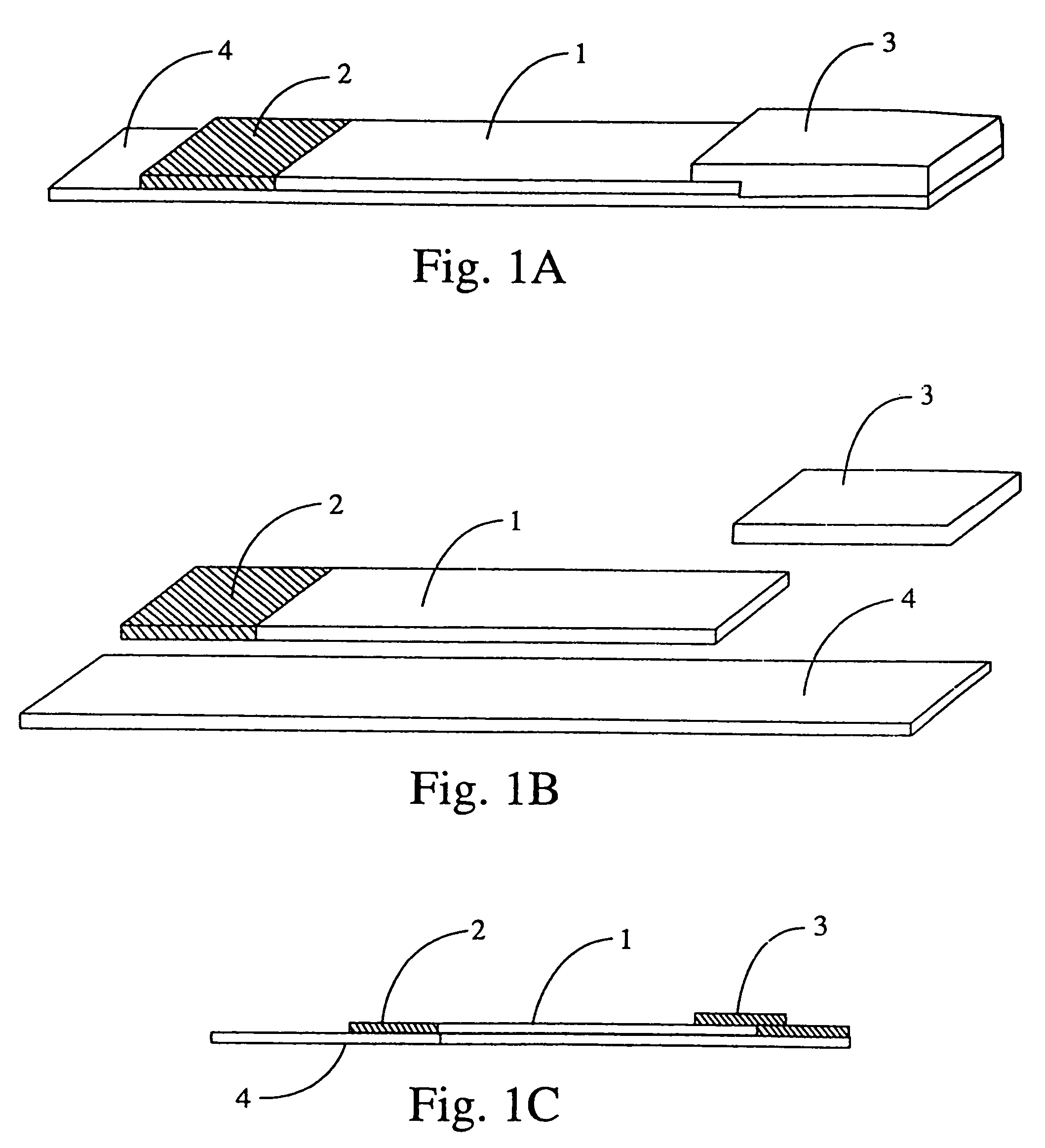
[0140]A test strip is manufactured according to the description given in FIG. 1. The backing 4 is extended in length beyond the absorbent pad 3 end to allow application of bar codes, fluorescent markings, and other indicators to the backing 4. Reagent zone 2 contains streptavidin conjugated magnetic particles, buffers, stabilizers, surfactants, and other reagents in dry form.

[0141]The test strip 11 is inserted absorbent pad 3 end first into the optical tunnel 9. Indicators on the test strip are interpreted as calibration information by the analyzer. For example, the analyzer verifies that the same bar code was read at both focal points 8a and 8b and stores reflectance and fluorescence values for photodetectors 13 and 16. The calibration information and measured values are used by the analyzer to verify the quality and structure of an individual capture line as well as the amount of analyte, control, or calibrator present at the capture line, and to verify the performance of each opt...

example 2

[0148]Example 2 mirrors Example 1 but for the following differences:

[0149]Reagent zone 2 contains all test reagents prepackaged in unit dose dried form including: streptavidin conjugated magnetic particles, biotin conjugated anti-beta HCG, and fluorescent microsphere conjugated anti-alpha HCG which cooperatively bind HCG molecules present in the sample. Reagent zone 2 also contains buffers, stabilizers, surfactants, and other reagents in dry form.

[0150]The operator adds a measured volume of test solution directly to reagent zone 2.

example 3

[0151]Example 3 mirrors Example 2 but for the following differences:

[0152]Anti-alpha HCG is conjugated using alkaline phosphatase, instead of fluorescent micro spheres.

[0153]A measured volume of fluorescent substrate is added to the reagent zone 2 subsequent to the addition of a measured volume of wash solution.


PUM

PropertyMeasurementUnit
areasaaaaaaaaaa
lengthaaaaaaaaaa
widthaaaaaaaaaa

Abstract

Novel magnetic assay methods and systems. According to a preferred embodiment, a chromatographic medium is provided that is designed to be contacted with a test solution having activated magnetic particles such that the solution flows bilaterally thereacross. A magnetic field, generated by a magnet or electromagnet, is selectively applied to the medium which causes the charged particles to become substantially bound at a site on the medium specified by the position of the magnet, to thus form a captured line or zone. In one preferred embodiment, the magnetic field is applied at the site on the medium at which the test solution is contacted. The assay is multi-configurable and can be modified to suit a particular immuno-separation procedure or application.

Description

CROSS-REFERENCE TO RELATED APPLICATIONS[0001]The present application is a continuation-in-part of U.S. application Ser. No. 10 / 068,040, filed Feb. 5, 2002, now U.S. Pat. No. 6,991,912 SYSTEMS AND METHODS FOR PERFORMING MAGNETIC CHROMATOGRAPHY ASSAYS, which is a divisional patent application of U.S. patent application Ser. No. 09 / 668,966, filed Sep. 25, 2000, and now issued as U.S. Pat. No. 6,713,271 on Mar. 30, 2004, which was a continuation-in-part of U.S. patent application Ser. No. 09 / 418,864, filed Oct. 15, 1999, and now issued as U.S. Pat. No. 6,136,549, issued on Oct. 24, 2000.STATEMENT RE: FEDERALLY SPONSORED RESEARCH / DEVELOPMENT[0002]Not ApplicableBACKGROUND[0003]Ligand-receptor assays or immunoassays are well-known in the art. Since their introduction in 1971, such assays have been utilized in a variety of applications to detect minute amounts of hormones, drugs, antibodies, and other substances suspected of being present in a given fluid sample. In this regard, researchers...

Claims


Application Information

Patent Timeline
Patent Type & Authority Patents(United States)
IPC IPC(8): G01N33/53G01N33/553
CPCG01N30/90G01N33/558G01N33/553G01N30/74Y10S436/807G01N33/54326
Inventor FEISTEL, CHRISTOPHER
Owner WAVESENSE INC
Why Eureka
Try Eureka