Electronic proximity switch

a proximity switch and electronic technology, applied in the field can solve the problems of easy triggering of sensitive electronic components easy triggering of electronic proximity switches, etc., and achieve the effect of high resistance to false triggering

Active Publication Date: 2008-07-01
ILLINOIS TOOL WORKS INC
View PDF13 Cites 6 Cited by
  • Summary
  • Abstract
  • Description
  • Claims
  • Application Information

AI Technical Summary

Benefits of technology

[0008]The present invention provides a simple electronic proximity switch that is highly resistant to false triggering and to changes in component values over time or with temperature.
[0009]Generally, the invention transmits an oscillator signal along two paths and then compares the relative strength of the signal along those paths. One path passes through an antenna that may couple with a sensed object to reduce the strength of the signal along that path. The use of two paths neutralizes the effect of any change in the signal strength from the oscillator that would affect the signal in both paths equally, allowing the circuit to be highly sensitive to changes caused by the sensed object.

Problems solved by technology

A significant problem with electronic proximity switches is their susceptibility to unintended triggering.
This can occur in electronic proximity switches that are used outdoors, such as with automotive door lock applications, where there is a risk that rain or debris carried in the wind could activate the switch.
Further, the sensitive electronics of the electronic proximity switch often can be triggered by electromagnetic interference, for example, from electrical appliances, radio transmitters, or lightning discharge.
Steps to avoid these problems can increase the complexity and cost of the electronic proximity switch, rendering it impractical for many consumer applications.

Method used


Image

  • Electronic proximity switch
  • Electronic proximity switch
  • Electronic proximity switch

Examples


Embodiment Construction

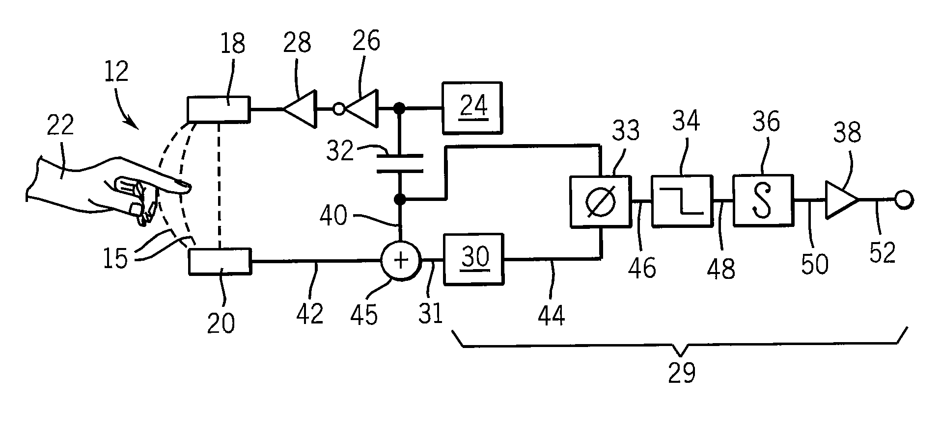
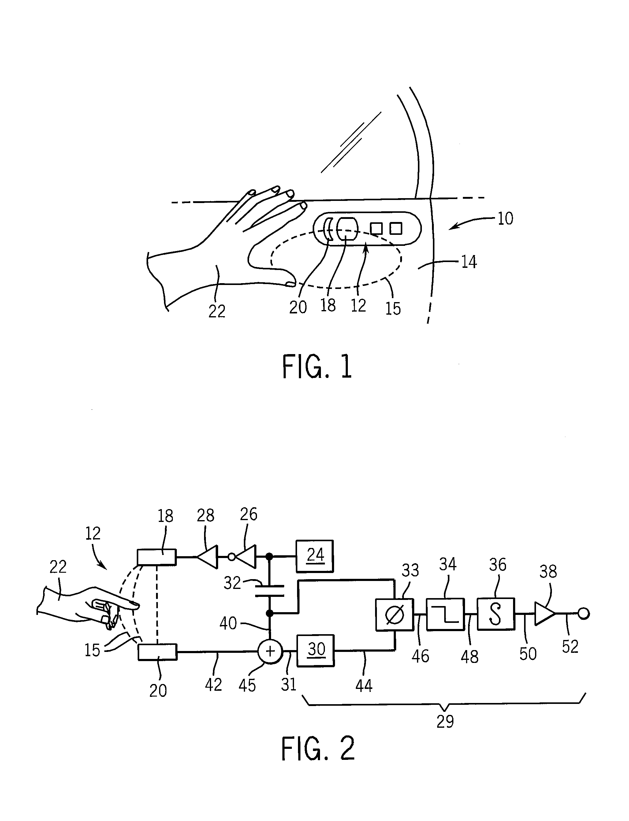
[0032]Referring now to FIG. 1, the present invention provides a electronic proximity switch 10 that may, for example, form part of a keyless entry system on an automobile or the like.

[0033]In this embodiment, the proximity switch 10 provides an antenna 12 formed as part of a handle escutcheon on an automobile door 14. The antenna 12 provides a first conductive plate 18 insulated from, but adjacent to, a second conductive plate 20, both of which may be visible or covered beneath a plastic face of the escutcheon. A person's hand 22 approaching the antenna 12 disrupts an electrical field 15 extending between the conductive plate 18 and the second conductive plate 20. Disruption of the electrical field is sensed to produce an electrical signal that may be used to actuate a door release mechanism or the like.

[0034]Referring now to FIG. 2, the conductive plate 18 and second conductive plate 20 are part of a first conductive path extending between oscillator 24 and oscillator 30 and furthe...


PUM


Abstract

An electronic proximity switch employs two oscillators coupled through two electrical paths, one associated with an antenna serving as a proximity switch sensor. Absorption by an object near the antenna changes the coupling between the oscillators producing a dramatic phase shift that may be detected and used for switching purposes.

Description

CROSS-REFERENCE TO RELATED APPLICATIONS[0001]This application claims the benefit of U.S. Provisional Application No. 60 / 674,787, filed Apr. 26, 2005.STATEMENT REGARDING FEDERALLY SPONSORED RESEARCH OR DEVELOPMENTBACKGROUND OF THE INVENTION[0002]The present invention relates to electronic proximity switches, and in particular to an electronic proximity switch which is highly resistant to mechanical and electrical noise and to temperature changes.[0003]Electronic proximity switches may detect the presence of an object, for example, a human hand near a switch plate, to provide an electrical signal that may be used to switch a circuit or activate a mechanism. Unlike a typical mechanical switch, an electronic proximity switch does not require moving parts, such as a button or switch operator, that may wear or break. Because an electronic proximity switch may activate at a distance, it can be more readily sealed against environmental contamination and protected from damage. Further, activ...

Claims


Application Information

Patent Timeline
Patent Type & Authority Patents(United States)
IPC IPC(8): G08B13/08
CPCE05F15/00H03K17/955E05Y2400/86E05Y2800/106E05Y2800/00H03K2217/96072E05Y2800/426
Inventor RICHARDS, THOMAS C.
Owner ILLINOIS TOOL WORKS INC
Why Eureka
Try Eureka