Mounting structure of electronic apparatus in vehicle

a technology of electronic equipment and mounting structure, which is applied in the direction of electric propulsion mounting, battery/cell charging, transportation and packaging, etc., can solve the problems of increased length of electric resistance of electric cables, decreased motor drive efficiency, and prone to malfunction of electronic equipment, so as to facilitate the removal and easy removal of the effect of the mounting operation of the system

Inactive Publication Date: 2008-07-15
MITSUBISHI FUSO TRUCK AND BUS CORPORATION
View PDF10 Cites 35 Cited by
  • Summary
  • Abstract
  • Description
  • Claims
  • Application Information

AI Technical Summary

Benefits of technology

[0013]The present invention was made to solve the problems of prior art mentioned above and its object is to provide a structure for mounting electronic apparatuses to a vehicle in an electric motor-driven vehicle, in which the electronic apparatuses such as a high voltage battery unit and motor control unit can be mounted compactly in the same section with a minimum mounting space, as a result it becomes possible to mount them even in a vehicle of rather short wheelbase, driving efficiency of the electric motor can be improved by reducing the length of cables for transferring high voltage electric power, and by increasing a mounting space for accessories other than those relating to driving power of the vehicle.

Problems solved by technology

In the prior art, there are problems that,(1) As the battery unit 1 and motor control unit 2 are located apart from each other and they are connected with electric cables, motor drive efficiency decreases by increased electric resistance of the electric cables increased in length, and malfunction is apt to occur in electronic apparatuses due to influence of electromagnetic waves generated by high voltage carrying cables.(2) As the motor control unit 2 is located in the lower part of the mounting space 55, the space for mounting refrigerating means, etc. is reduced and ease of mounting them is deteriorated.

Method used


Image

  • Mounting structure of electronic apparatus in vehicle
  • Mounting structure of electronic apparatus in vehicle
  • Mounting structure of electronic apparatus in vehicle

Examples


Embodiment Construction

[0048]A preferred embodiment of the present invention will now be detailed with reference to the accompanying drawings. It is intended, however, that unless particularly specified, dimensions, materials, relative positions and so forth of the constituent parts in the embodiments shall be interpreted as illustrative only, not as limitative of the scope of the present invention.

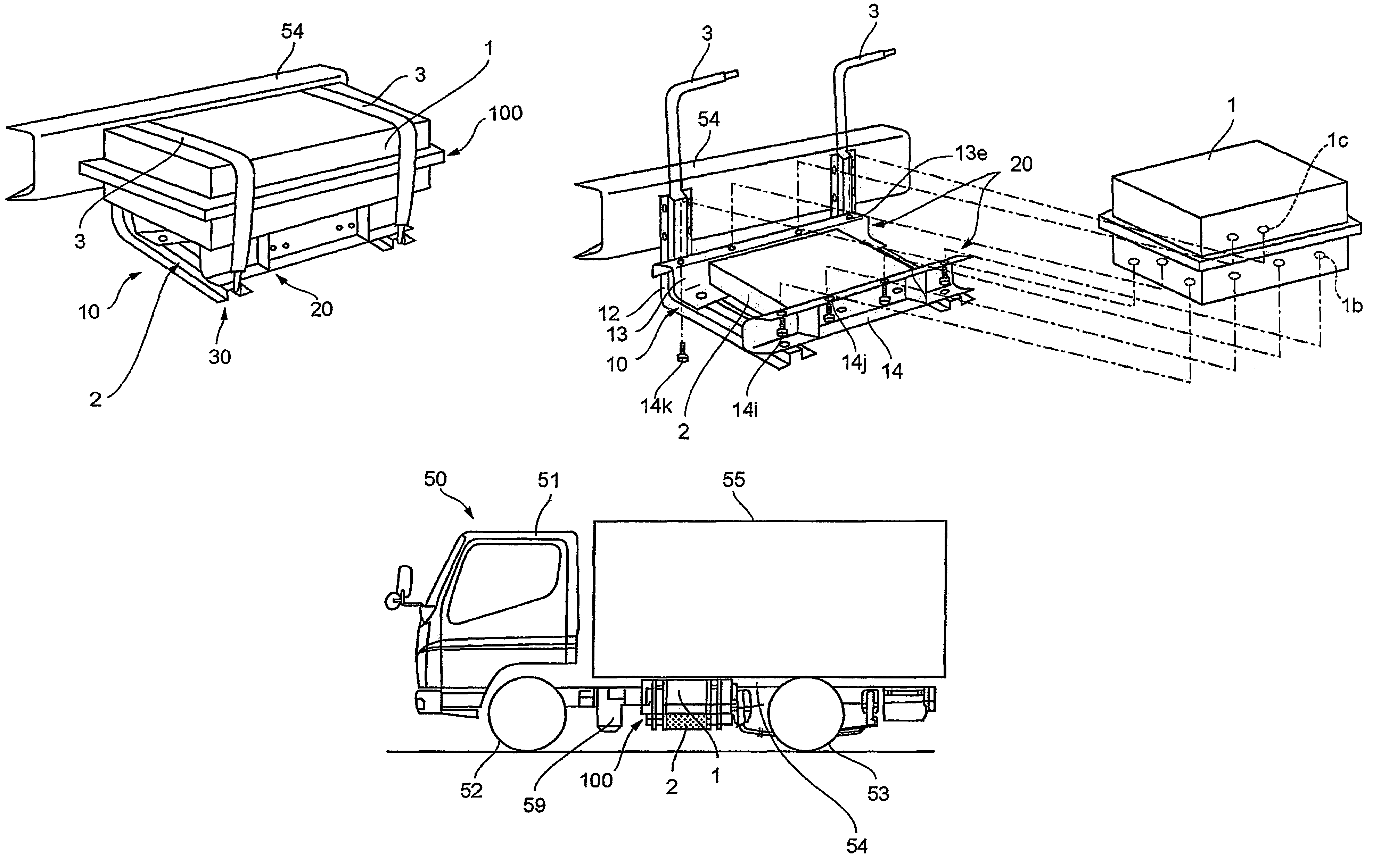
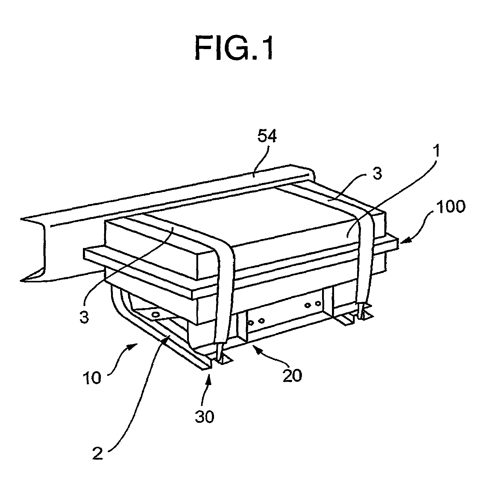
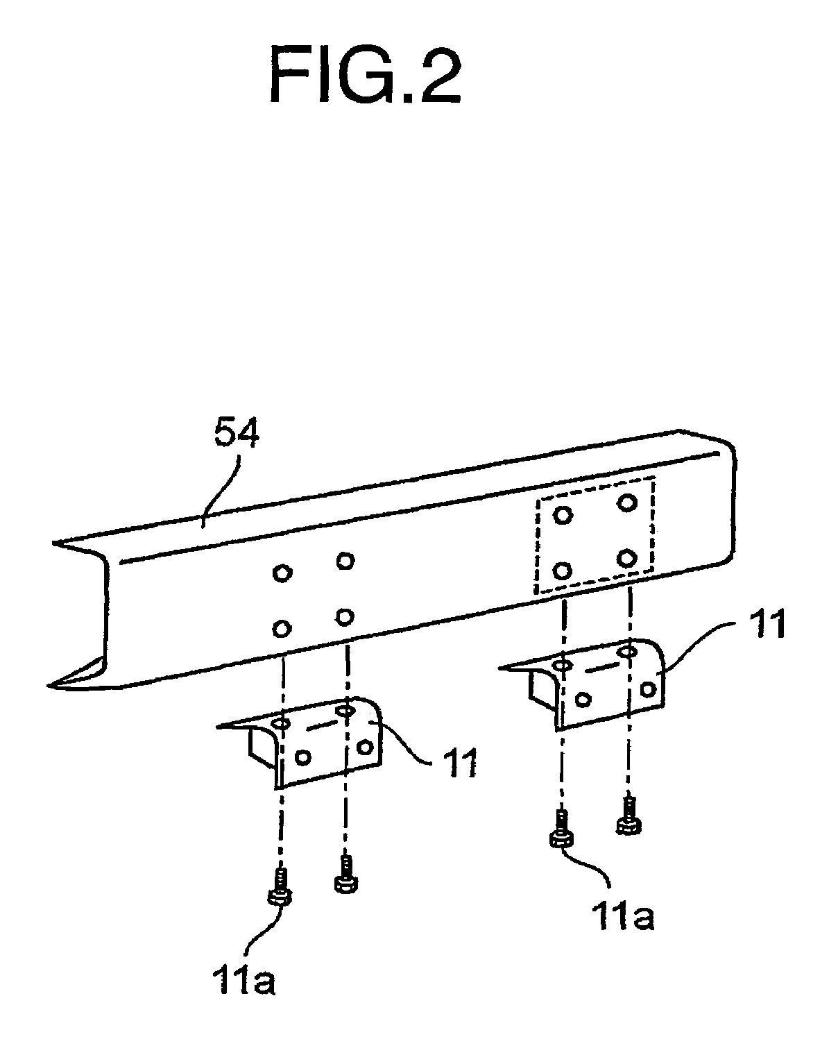
[0049]FIG. 7 is a side elevation of the embodiment of a hybrid powered refrigeration car mounted with a combination of a diesel engine 60 and an electric motor 61 according to the present invention, and FIG. 8 is a plan view of the embodiment. In FIGS. 7 and 8, reference numeral 50 is a vehicle, 51 is a cabin of the vehicle 50, 54 is a pair of right and left chassis frames, 52 are front wheels, 53 are rear wheels, and 55 is a mounting space for mounting a refrigeration system.

[0050]Reference numeral 2 is a motor control unit (electronic apparatus unit of the vehicle) for controlling said motor 61 for driving wh...


PUM


Abstract

A structure for mounting electronic apparatuses in an electric motor-driven vehicle has a pair of first brackets each having a base part that is fixed to the side face of a chassis frame extending in the longitudinal direction of the vehicle and an arm part extending in the lateral direction of the vehicle. A pair of second brackets is fixed to the upper surfaces of the arm parts such that they extend in the longitudinal direction of the vehicle with a space between them. A battery unit is placed on the upper surfaces of the second brackets, and an electronic apparatus unit is placed under the battery unit between the second brackets. The structure enables electronic apparatuses to be mounted compactly, improves the efficiency of the electric motor by reducing the length of high voltage electric cables, and increases the available space for mounting the refrigerating system.

Description

CROSS-REFERENCE TO RELATED APPLICATION[0001]This application claims the benefit of priority to JP 2004-313160 filed Oct. 27, 2004.FIELD OF THE INVENTION[0002]The present invention relates to a mounting structure of electronic apparatuses in a motor-driven vehicle which has electronic apparatuses for controlling said motor and a battery unit which constitute an electric power source for said apparatuses.DESCRIPTION OF THE RELATED ART[0003]FIG. 9 is a plan view of a hybrid powered refrigeration car mounted with a diesel engine / electric motor combination.[0004]In the drawing, reference numeral 51 is a cabin, 54 is a chassis frame, 53 are rear wheels, 55 is a mounting space for a refrigeration system.[0005]Reference numeral 2 is a motor control unit to control a motor for driving the car, 1 is a high voltage battery unit constituting the electric source for said motor and motor control unit. Said high voltage battery unit 1 is attached to a side part of the chassis frame 54 between fron...

Claims


Application Information

Patent Timeline
Patent Type & Authority Patents(United States)
IPC IPC(8): B60R16/04
CPCB60K1/04B60L11/18B60L11/1877B60R16/04Y02T90/124Y02T10/7005Y02T10/705B60L2200/36B60L50/60B60L50/66Y02T10/70B60K6/28B60P3/20B60Y2200/91B60Y2200/92Y02T90/12
Inventor YOSHIDA, KEI
Owner MITSUBISHI FUSO TRUCK AND BUS CORPORATION
Why Eureka
Try Eureka