Lens array with integrated folding mirror

a technology of folding mirrors and arrays, applied in optics, instruments, optical light guides, etc., can solve the problems of increasing optical and electrical signal losses, increasing bandwidth demand in fiber communication systems, and potential loss of optical components, so as to avoid long lead/cable length, facilitate connection, and reduce the effect of cable length

Inactive Publication Date: 2008-07-15
LOCKHEED MARTIN CORP
View PDF9 Cites 95 Cited by
  • Summary
  • Abstract
  • Description
  • Claims
  • Application Information

AI Technical Summary

Benefits of technology

[0007]In light of the aforementioned problems, it is one object of the present invention to provide a lens array that permits the creation of a multi-channel fiber optic transceiver assembly that is substantially smaller than previous assemblies while allowing for performance at high data rates and optimum cable routing. A second object of the present invention is to eliminate long electrical leads between the lasers or detectors of the transceiver and the related amplifier chips thereby allowing data to be transmitted at higher data rates while reducing signal loss. A third object of the present invention is to provide better compatibility for standard pick and place automated assembly and manufacturing practices thus lowering costs.
[0010]Due to the positioning of components in the transceiver assembly, many of the above-mentioned advantages are obtained. Easy connection to the fiber optic cable is achieved due to the configuration of the lens array. Further, efficient coupling to the optoelectric components is achieved in a manner that avoids long lead / cable length. This is made possible due to the placement of these optoelectric components directly on the circuit board, and the positioning of the lens array directly there above.

Problems solved by technology

Unfortunately, these optical components are potential sources of signal loss due to contamination or imperfections.
Demand for bandwidth in fiber communication systems is limitless.
It is commonly known that, both optical and electrical signal losses increase as the number of components and connections in a fiber optic system are increased.
These signal losses are very critical given the high frequency at which these systems operate.
These connections can be a source of signal loss, and often result in reductions in performance because of the electrical lead lengths.

Method used


Image

  • Lens array with integrated folding mirror
  • Lens array with integrated folding mirror
  • Lens array with integrated folding mirror

Examples


Embodiment Construction

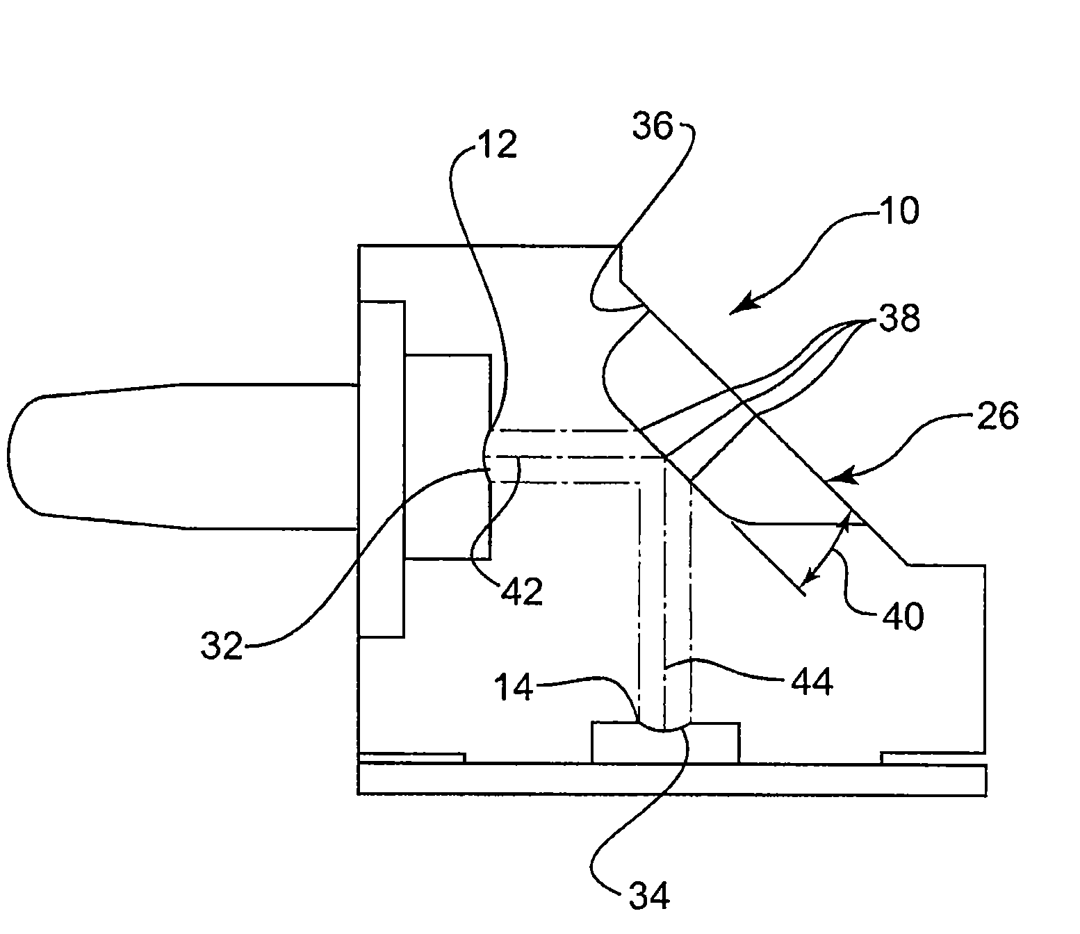
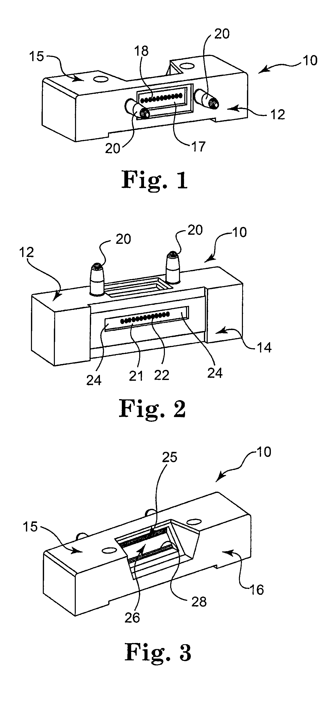
[0025]Referring now to FIGS. 1-3 there is shown a lens array 10 in accordance with the present invention. Lens array 10 is depicted as a substantially rectangular component, which includes a fiber side 12, a device side 14 and a back side 16. In addition, lens array 10 includes a top side 15 (as more specifically shown in FIG. 7). Those skilled in the art can appreciate that the size and shape of lens array 10 can be varied depending on the type of fiber optic connector and / or device to which it is coupled. In one embodiment of the present invention all non-critical surfaces of lens array 10 have a frosted or otherwise textured surface to facilitate adhesion of lens array 10 to other components in a fiber optic transceiver assembly.

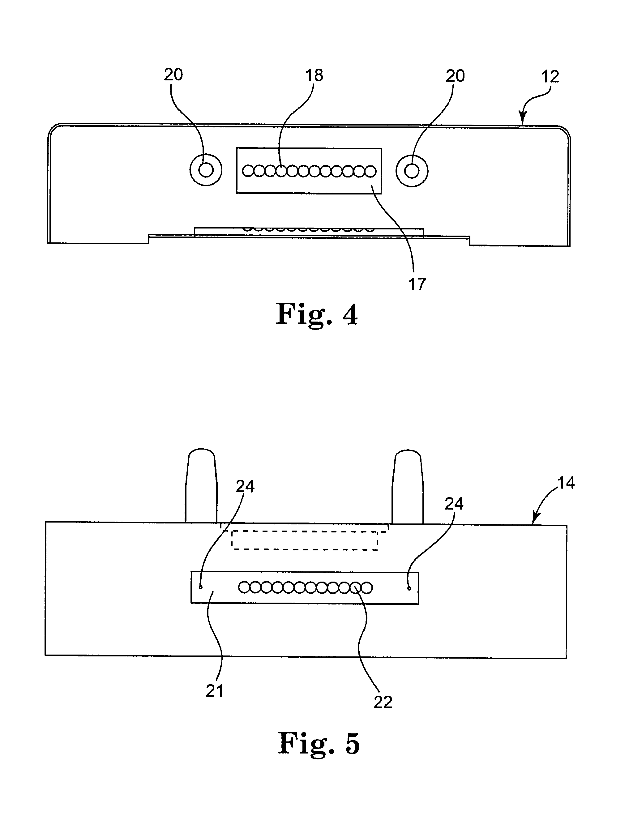
[0026]Fiber side 12 is shown in greater detail in FIG. 4. Fiber side 12 has a connector receptacle 17 with a plurality of fiber side optical openings 18. FIG. 4 depicts a total of twelve fiber side optical openings 18; however those skilled in the art can...


PUM


Abstract

A fiber optic transceiver incorporating a lens array with an integrated mirror and method of creating the same is disclosed. The transceiver includes the lens array and transceiver housing used to convert optical signals to electrical signals. The lens array includes a fiber side that can be connected to a fiber optic connector. The lens array also has a device side that can be connected to a photodetector. The lens array also includes a mirror that is positioned to transmit an optical signal received from the fiber side to the device side. Both the fiber side and the device include lenses used to provide focused transmission of optical signals. Accordingly, optical signals can be transmitted from a fiber optic connector to a photodetector in a compact and efficient manner at high bandwidths.

Description

BACKGROUND OF THE INVENTION[0001]The present invention relates to a fiber optic transceiver having efficient connection structure. More specifically, the present invention relates to a fiber optic transceiver assembly that receives and transmits at faster data rates while reducing signal loss by incorporating a compact lens array having an integrated folding mirror.[0002]Modern fiber telecommunication and data communication systems use transmitter / receiver components, commonly known as transceivers. As is well known, fiber optic transceivers facilitate bi-directional signal transmissions between electronic devices and fiber optic system components. The transceivers include photodetectors, which convert received optical signals to electric signals which can then be used by many electronic devices. Photodetectors are typically positioned at the receiving end of the fiber optic data, video, or audio link. The most common photodetector is the semiconductor photodiode, which produces cur...

Claims


Application Information

Patent Timeline
Patent Type & Authority Patents(United States)
IPC IPC(8): G02B6/36
CPCG02B6/4204G02B6/4249G02B6/4292
Inventor WHALEY, GREGORY J.KARNOPP, ROGER J.
Owner LOCKHEED MARTIN CORP
Why Eureka
Try Eureka