
Method and system for reticle-wide hierarchy management for representational and computational reuse in integrated circuit layout design

a technology of representational and computational reuse and layout design, applied in the field of integrated circuit design process, can solve problems such as failure to take into account distortion caused by other factors, and achieve the effect of saving representational data volume and maximizing reus

Active Publication Date: 2008-07-15
CADENCE DESIGN SYST INC
View PDF22 Cites 16 Cited by
  • Summary
  • Abstract
  • Description
  • Claims
  • Application Information

AI Technical Summary

Benefits of technology

[0020]One of the primary objectives of hierarchy management is to maximize reuse, in both representation and computation. A hierarchical representation encapsulates the detailed internal composition of a sub-circuit using the notion of a cell definition (a CellDef). The cell definition is then used or referred to in other cell definitions, possibly many times. Without having to repeat the detailed composition of the cell, a reference to the CellDef requires a minimal amount of information. Very significant savings in representational data volume can thus be accomplished.
[0027]In yet another aspect, the invention is directed to the distribution of the computational task for an integrated circuit layout design on a reticle field wide basis among a collection of networked computation nodes. This enables better concurrent execution, lowering turn around time.
[0038]In a preferred embodiment, a pre-processing step creates clusters of primitive geometries into primitive unit cells, and provides each such cell with a unique numerical identifier. In the operation of trying to determine the identity of proximity environments, computational time is reduced by using these numerical identifiers, rather than by comparing elements of the primitive geometries in the adjacent regions of each instance.

Problems solved by technology

For example, while conventional OPC techniques address some of the higher order distortions that occur between the layout pattern and the pattern formed in the photo-resist due to proximity effects, they fail to take into account distortions caused by other factors, such as position of the features in the reticle field or structural functionality requirements of the electrical components.

Method used


Image

  • Method and system for reticle-wide hierarchy management for representational and computational reuse in integrated circuit layout design
  • Method and system for reticle-wide hierarchy management for representational and computational reuse in integrated circuit layout design
  • Method and system for reticle-wide hierarchy management for representational and computational reuse in integrated circuit layout design

Examples


Embodiment Construction

[0072]Hierarchical Representation

[0073]A hierarchical representation of a chip layout design comprises primarily a collection of data objects or structures: a set of cell definitions (CellDef's).

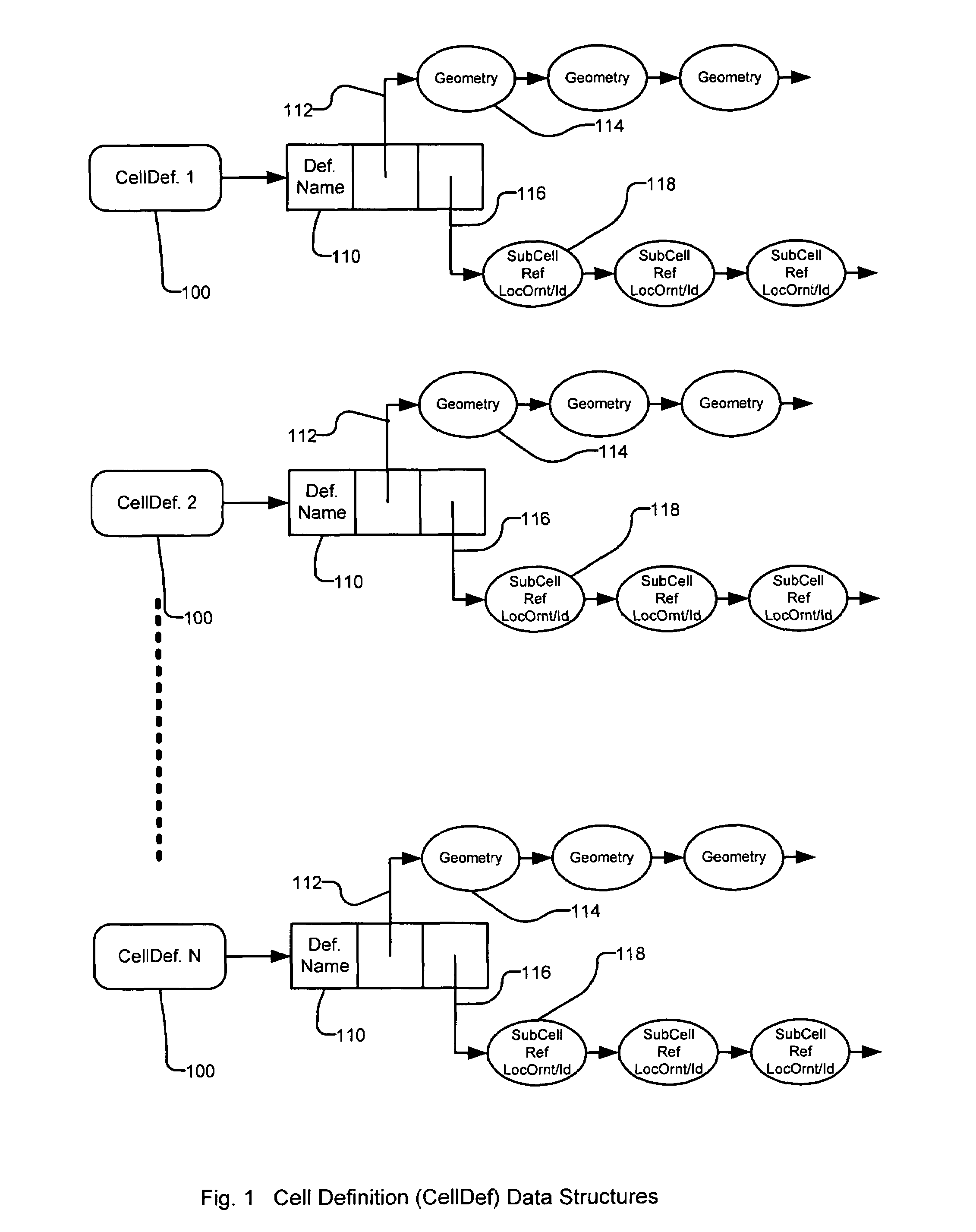
[0074]FIG. 1 shows how the cell definitions may look in such a layout design.

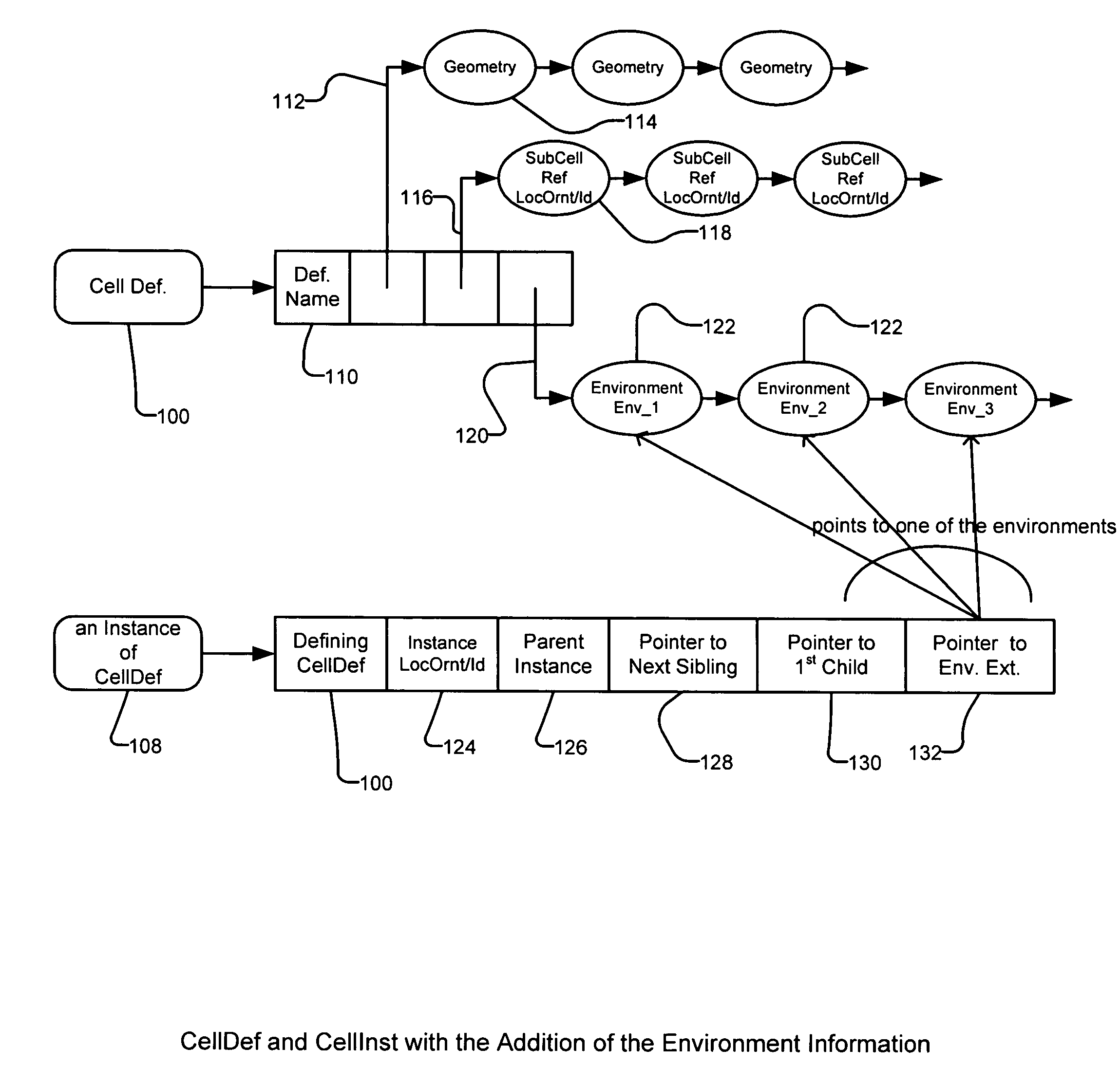
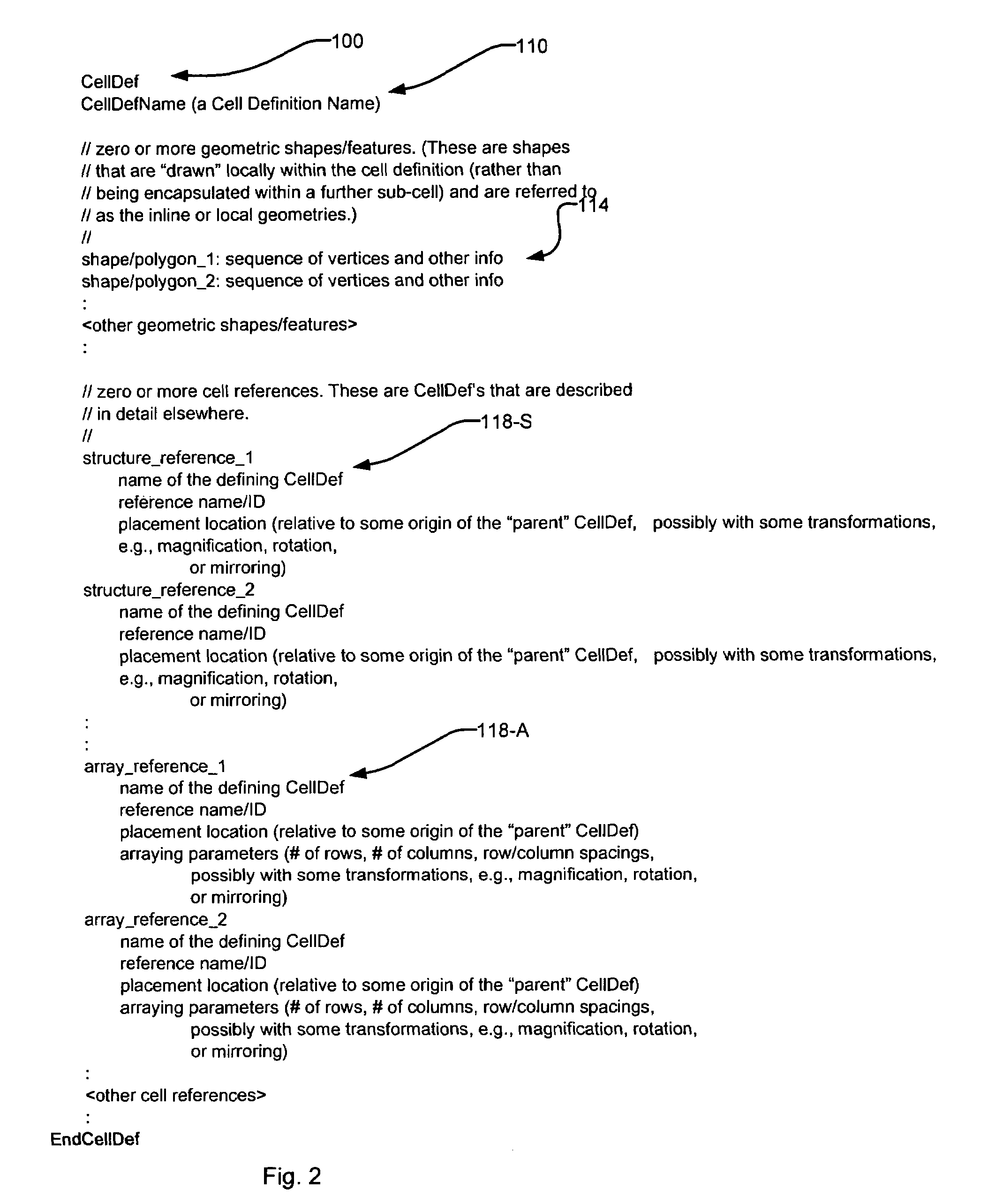
[0075]Specifically, the cell definitions are data objects or data structures that describe recurring patterns within the layout design. Each cell definition CellDef1, CellDef2, . . . CellDef N 100 is typically characterized by a name for the cell 110. Further within the cell definition is typically a pointer 112 to the geometry information 114. This geometry information 114 may contain one or more (possibly a very large number of) geometric features (polygons, lines, holes, rectangles, paths, texts . . . , etc.). Such geometric features are called inline geometries of the CellDef. Within the CellDef, sub-cell pointers 116 are also commonly provided. These are pointers to nested sub-cells 118 that may contain further...


PUM

PropertyMeasurementUnit
sizeaaaaaaaaaa
optical proximityaaaaaaaaaa
physical designaaaaaaaaaa

Abstract

A hierarchical representation encapsulates the detailed internal composition of a sub-circuit using the notion of a cell definition (a CellDef). The CellDef serves as a natural unit for operational reuse. If the computation required for the analysis or manipulation (e.g. parasitic extraction, RET, design rule confirmation (DRC), or OPC) based on a CellDef or one cell instance can be applied, with no or minimal additional effort, to all or a significant subset of other instances of the cell, very substantial reduction in computational effort may be realized. Furthermore, a hierarchical representation also allows for the partitioning of the overall analysis / manipulation task into a collection of subtasks, e.g. one per CellDef. Multiple jobs may then be distributed across a large number of computational nodes on a network for concurrent execution. While this may not reduce the aggregate computational time, a major reduction in the overall turnaround time (TAT) is in itself extremely beneficial.

Description

BACKGROUND OF THE INVENTION[0001]The process of designing integrated circuits typically involves a functional design step, followed by a physical design step. During the functional design step, a design concept is described using a hardware description language and is then converted into a netlist, which specifies the electronic components and the connections between the components. The physical design step specifies the placement of the electronic components or elements on the chip and routing of the connections between the electronic components, thereby implementing the netlist. The physical design process generates the physical design data, which are synonymously called layout data, layout, or target layout.[0002]The layout data defines a set of binary patterns or objects, which are also called “geometric features” or “features”. Usually the objects are represented as a polygon or collection of polygons in the layout data in order to facilitate the specification of the objects.[0...

Claims


Application Information

Patent Timeline
Patent Type & Authority Patents(United States)
IPC IPC(8): G06F17/50G03F1/00G06F19/00G21K5/00
CPCG06F17/5072G06F2217/12G06F2119/18G06F30/392Y02P90/02
Inventor HORNG, CHI-SONGJOSHI, DEVENDRALIU, ANWEI
Owner CADENCE DESIGN SYST INC
Learn More