Fuel injection device for internal combustion engine

a fuel injection device and internal combustion engine technology, applied in the direction of relays, machines/engines, electric control, etc., can solve the problems of ineffective injection time, shortage of actual injection time, etc., to prevent the reduction of battery voltage, prevent the shortage of fuel injection amount, and prevent the loss of ignition operation.

Inactive Publication Date: 2008-07-22
KOKUSAN DENKI CO LTD
View PDF15 Cites 7 Cited by
  • Summary
  • Abstract
  • Description
  • Claims
  • Application Information

AI Technical Summary

Benefits of technology

[0012]An object of the present invention is to provide a fuel injection device for an internal combustion engine that performs a fuel injection operation with a large current passing through a load other than an injector, and prevents a reduction in a battery voltage and an increase in ineffective injection time in the process of opening a valve of the injector, thereby preventing a shortage of fuel injection amount.

Problems solved by technology

Time between when the injector receives the driving voltage and when the injector starts the injection of the fuel is referred to as an ineffective injection time.
If the driving voltage is reduced in the opening process of the valve of the injector to increase the ineffective injection time, the actual injection time is reduced to cause a shortage of fuel injection amount.
If the driving voltage applied from the battery to the injector is significantly reduced, the ineffective injection time may be increased to cause a shortage of actual injection time and a shortage of fuel injection amount.
However, if the injector is not driven while the current passes from the battery through the ignition device, and a period in which a large current passes from the battery through the ignition device matches a period in which the injector is driven, fuel injection to be performed is not performed, thereby causing another problem of a shortage of amount of fuel supplied to the engine.
There is no problem if the period in which the large current passes from the battery through the ignition device does not match the period in which the injector is driven, but it is difficult that the period in which the current passes through the ignition device does not match the period in which the injector is driven both during low speed rotation and high speed rotation.
In this case, however, the injector is driven with the current passing from the battery through the ignition device, and thus the problem cannot be solved that the battery voltage is reduced in the process of opening the valve of the injector to cause the shortage of fuel injection amount.

Method used


Image

  • Fuel injection device for internal combustion engine
  • Fuel injection device for internal combustion engine
  • Fuel injection device for internal combustion engine

Examples


Embodiment Construction

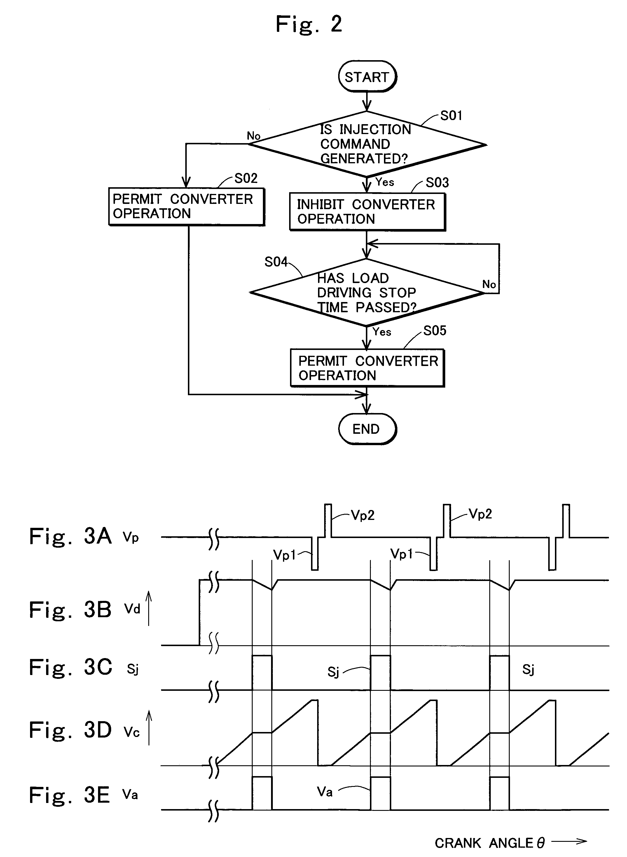
[0034]Now, a preferred embodiment of the present invention will be described in detail with reference to the drawings.

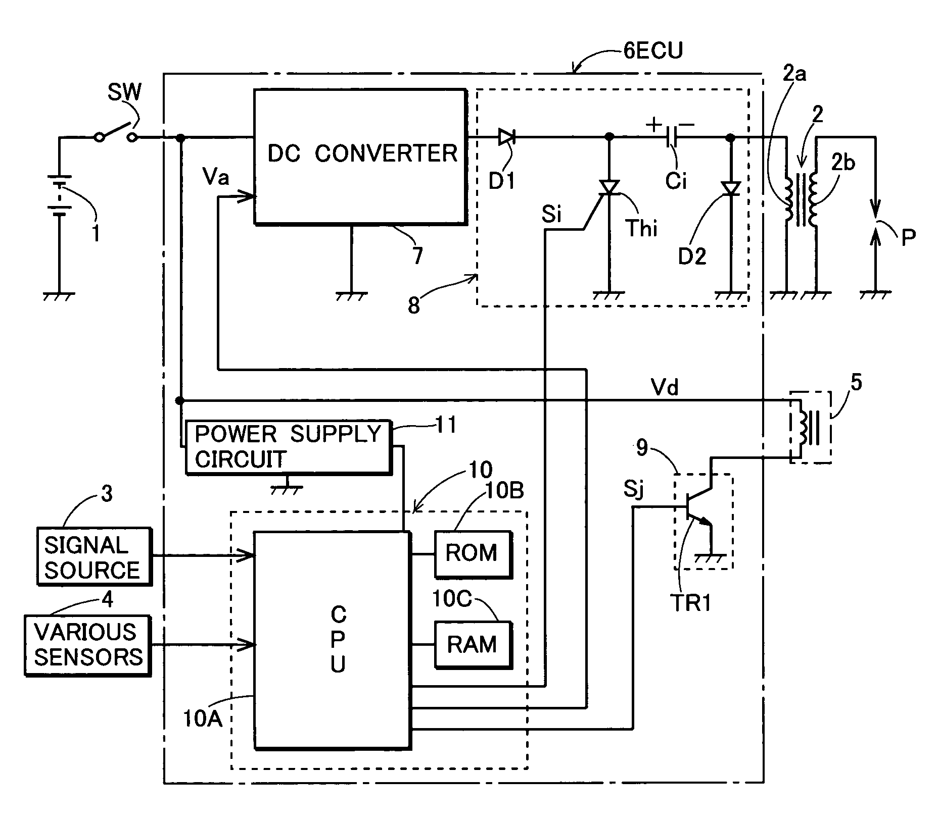
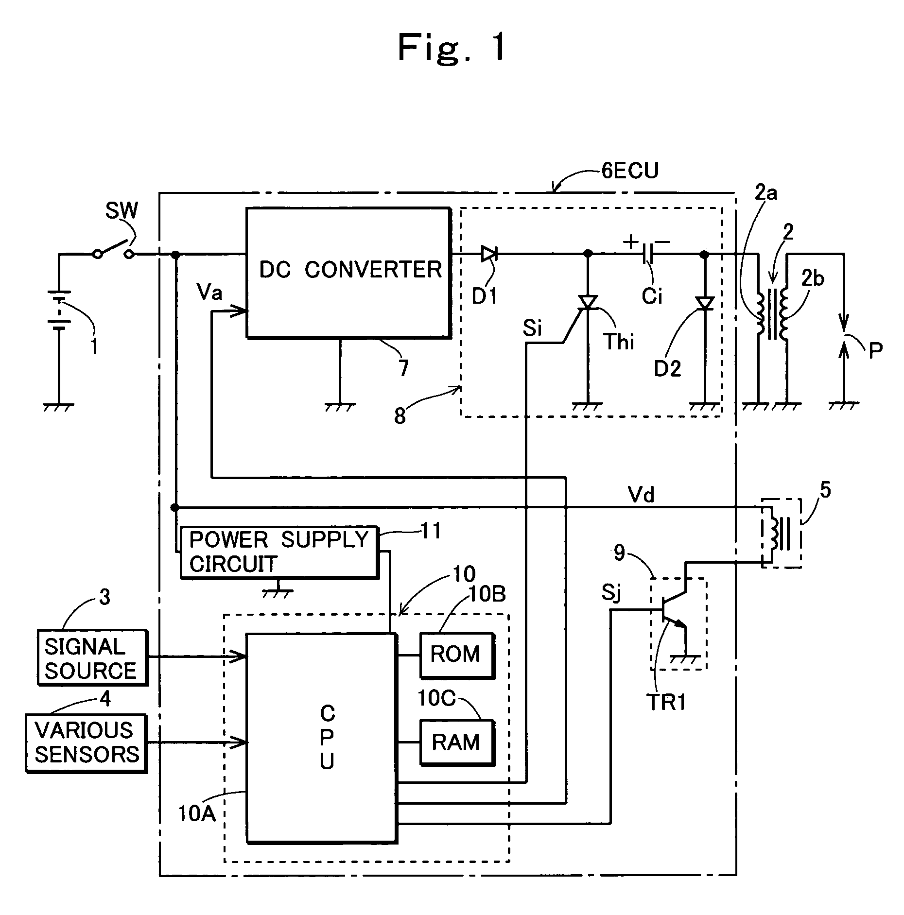
[0035]FIG. 1 shows an exemplary configuration of hardware of a fuel injection device according to the present invention. In FIG. 1, a reference numeral 1 denotes a battery having a grounded negative terminal; 2, an ignition coil; 3, a signal source that generates a pulse signal at a predetermined crank angle position of an engine in synchronization with rotation of the engine; 4, various sensors that detect control conditions required for arithmetically operating fuel injection time; 5, an injector that is mounted to an intake pipe of the engine and injects fuel into the intake pipe downstream of a throttle valve; and 6, an electronic control unit (ECU) that controls an ignition device and a fuel injection device. The sensors 4 include an intake air temperature sensor, a cooling water temperature sensor, an intake pipe internal pressure sensor, a throttle position se...


PUM


Abstract

A fuel injection device for an internal combustion engine including: an injector that injects fuel to be supplied to the internal combustion engine; a battery to which a DC converter that charges a capacitor of a capacitor discharge ignition circuit is connected as a load; a control portion that is provided to operate when a power supply voltage is provided from the battery through a power supply circuit, and generates an injection command signal when fuel injection timing is detected; and an injector drive circuit that applies a driving voltage from the battery to the injector while receiving the injection command signal, wherein the device further comprises converter operation stopping portion for stopping an operation of the DC converter during set load driving stop time when the injection command signal is generated.

Description

TECHNICAL FIELD OF THE INVENTION[0001]The present invention relates to a fuel injection device that supplies fuel to an internal combustion engine.BACKGROUND OF THE INVENTION[0002]A fuel injection device has been used as a device for supplying fuel to an internal combustion engine. The fuel injection device includes an injector having a valve driven by a solenoid, a fuel pump that supplies fuel to the injector, and a regulator that controls pressure of the fuel supplied from the fuel pump to the injector to be kept constant. When such a fuel injection device is used to supply the fuel to the internal combustion engine, the device includes an injector drive circuit that applies a driving voltage from a battery to the solenoid of the injector and passes a driving current through the solenoid while receiving an injection command signal, and a control portion that receives a power supply voltage from the battery through a power supply circuit and is mainly constituted by a microprocesso...

Claims


Application Information

Patent Timeline
Patent Type & Authority Patents(United States)
IPC IPC(8): F02M51/00
CPCF02D41/20F02P3/0876F02D2200/503
Inventor KIMURA, KENJISATO, HIROYASU
Owner KOKUSAN DENKI CO LTD
Why Eureka
Try Eureka