High performance air core motor-generator winding

a technology of air core motor and winding, which is applied in the direction of windings, magnetic circuit rotating parts, magnetic circuit shapes/forms/construction, etc., can solve the problems of armature failure, armature failure, and new larger air core motors for industrial applications that are faced with unpredictable armature failures, etc., to achieve high performance, longer and more reliable operating life, and high winding density

Inactive Publication Date: 2008-07-22
REVOLUTION ELECTRIC MOTOR
View PDF19 Cites 69 Cited by
  • Summary
  • Abstract
  • Description
  • Claims
  • Application Information

AI Technical Summary

Benefits of technology

[0004]The invention provides a new high performance air core motor-generator winding that affords longer and more reliable operating life, higher winding density and is easier to wind. The invention provides an air core motor-generator for converting between electrical and rotational energy. The motor-generator uses a rotor that is comprised of two spaced apart rotor portions that define therebetween an armature air gap, and magnetic poles on the rotor that drive flux across the air gap. Located in the armature airgap is a stator that is comprised of an armature having windings such that AC voltage is induced in the windings as the rotor rotates. To substantially reduce the eddy current losses that would otherwise occur in the actual windings, the windings are wound with Litz wire, or wire formed of bundled individually insulated conductors, wherein the conductors are electrically connected in parallel but are electrically insulated between each other along their length, and the conductors of the wire are held together by an outer insulating serve. The Litz wires replace a large diameter single strand magnet wire (copper wire with enamel film insulation) with many strands of smaller magnet wires that are insulated between each other but are all connected together at the ends. The smaller wire diameters exposed to a changing magnetic field substantially reduces the size of the eddy currents that are generated in the windings and the resulting losses. The overall cross-sectional area of conductor in the total wire can be chosen to be the same as the solid single magnet wire being replaced such that the resistive losses are the same. The special embodiments of the winding that facilitate the described benefits of the invention will be explained.

Problems solved by technology

The smaller wire diameters exposed to a changing magnetic field substantially reduces the size of the eddy currents that are generated in the windings and the resulting losses.
New larger air core motors for industrial applications are encountering unpredictable armature failures, despite seemingly standard manufacturing techniques.
Early on use of induction motors with variable speed drives resulted in armature failures because of voltage switching spikes from the inverter.
These failures are despite the fact that the inverter buss voltage and the voltage spikes were below the dielectric breakdown strength of the magnet wire used in the motors.
The problem causing the failure was attributed to the corona inception voltage of the insulation.
Unfortunately, this is not the case.
This technique has been found to be ineffective for use in new air core motors.
In a conventional motor, the probably of a pinhole from one turn being aligning with a pinhole from a subsequent turn and causing failure is insignificant.
The resulting probability of an eventual armature failure is not insignificant and these defects lead to eventual armature deterioration and failure.
Secondly, smaller diameter magnet wire strands, like those used in a Litz bundle, physically achieve a significantly thinner enamel insulation than larger solid single conductor wires because of the coating process.

Method used


Image

  • High performance air core motor-generator winding
  • High performance air core motor-generator winding
  • High performance air core motor-generator winding

Examples


Embodiment Construction

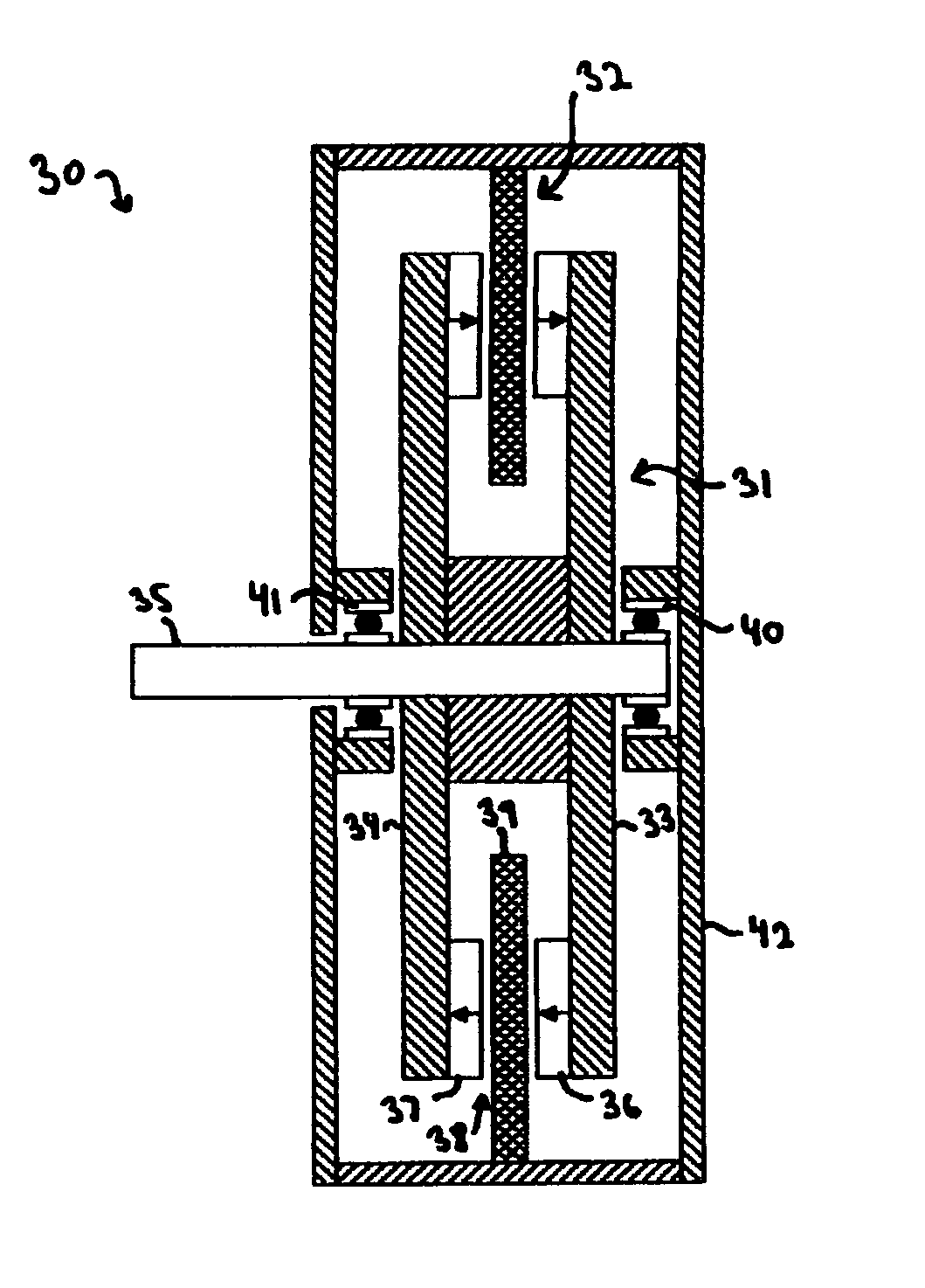
[0031]Turning to the drawings, wherein like reference characters designate identical or corresponding parts, FIG. 1 shows an axial gap double rotating air core motor-generator 30 having a rotor 31 mounted for rotation relative to a stationary stator 32. The rotor 31 includes two spaced apart discs 33, 34 that form therebetween an armature airgap 38. Magnetic poles 36, 37 drive magnetic flux across a magnetic airgap between the pairs of magnets. The magnetic poles 36, 37 are shown as circumferential arrays of alternating, axial polarity, permanent magnets and are located on both discs 33, 34. However, magnets can alternatively be located only on one disc 33, 34 and magnetic poles can also be made of steelprotrusions on the discs 33, 34, so long as a source of magnetic flux is provided to drive magnetic flux from the poles 36, 37 to traverse the magnetic airgap. An air core armature 39 is attached and supported at its outer diameter by a housing 42, and extends into the armature airga...


PUM


Abstract

A motor-generator for converting between electrical and rotational energy includes a rotor mounted for rotation about an axis of rotation relative to a stationary a stator that magnetically interacts with the rotor. The rotor has two spaced apart rotor portions that define therebetween an armature airgap. Magnetic poles on the rotor portions drive magnetic flux across the airgap. An air core armature is located in the airgap, such that opposite sides of the air core armature face the two opposed rotating surfaces of the rotor. The air core armature has windings in which AC voltage is induced as the rotor rotates. The windings are wound with multiple individually insulated strand conductor wire wrapped with a wrapping of a thin dielectric tape film over the multiple individually insulated strand conductor wire.

Description

[0001]This invention pertains to motor-generators for converting between electrical and rotational energy and more particularly to specialized wire windings for motor-generators that utilize an air core armature located in an armature airgap bounded on both sides by rotating surfaces of the rotor. The wire windings provide improved, longer and more reliable operating life, especially when coupled with motor drive inverters, increased motor-generator efficiency and are easier to wind into high winding density air core armatures.BACKGROUND OF THE INVENTION[0002]Air core motor-generators utilizing a double rotating construction have been developed. These electrical machines eliminate magnetic induced power losses in a steel stator and provide for high efficiency through elimination of the steel stator. A circumferentially varying magnetic flux thereby does not pass through a stationary steel structure and hence no hysteresis or eddy current losses in stationary steel result. An additio...

Claims


Application Information

Patent Timeline
Patent Type & Authority Patents(United States)
IPC IPC(8): H02K1/22
CPCH02K3/345H02K3/47H02K21/24H02K21/12
Inventor GABRYS, CHRISTOPHER W.
Owner REVOLUTION ELECTRIC MOTOR
Why Eureka
Try Eureka