DC offset calibration system
a calibration system and offset technology, applied in the field of dc offset calibration system, can solve the problems of reducing the sensitivity of receiving signals, the inability to achieve the perfect symmetry of the elements constituting the differential circuit, and the inability to eliminate secondary nonlinear distortion
- Summary
- Abstract
- Description
- Claims
- Application Information
AI Technical Summary
Benefits of technology
Problems solved by technology
Method used
Image
Examples
first embodiment
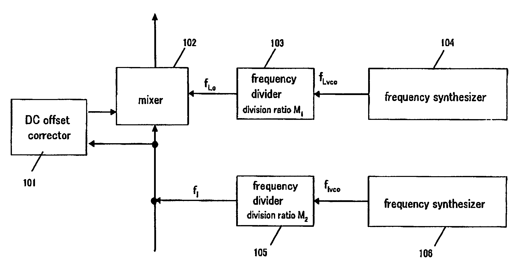
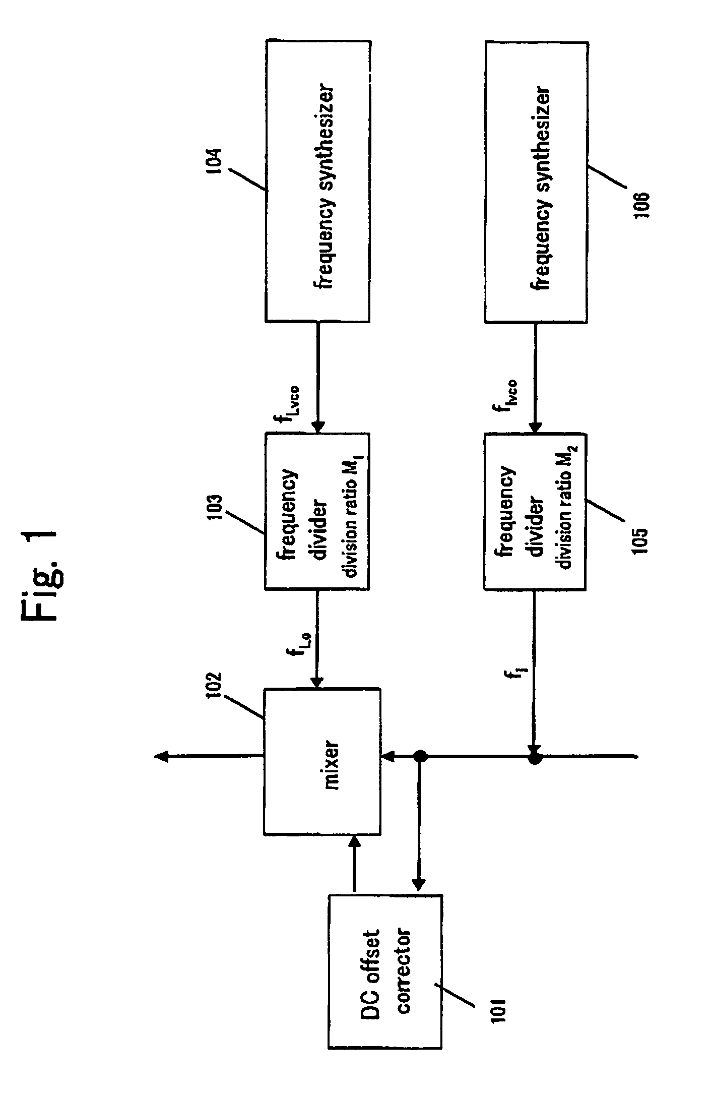
[0040]Referring first to FIG. 1, the present invention will be described. A frequency divider 103 divides the frequency of a frequency signal fLvco of a frequency synthesizer 104 at a division ratio M1, to thereby output a frequency signal fLo and input the frequency signal fLo to a mixer 102 as a local signal.
[0041]Likewise, a frequency divider 105 divides the frequency of a frequency signal fIvco of a frequency synthesizer 106 at a division ratio M2, to thereby output a frequency signal fI and input the frequency signal fI to the mixer 102 and a DC offset corrector 101 as a RF interfering signal. The DC offset corrector 101 has a similar configuration to FIG. 6.
[0042]Here, the relation among the local signal fLo, the frequency signal fLvco and the division ratio M1, as well as among the interfering signal fI, the frequency signal fIvco and the division ratio M2 can be defined as the following formulas (1) and (2).
fLo=fLvco / M1 (1)
fI=fIvco / M2 (2)
[0043]It is to be assumed that a ra...
second embodiment
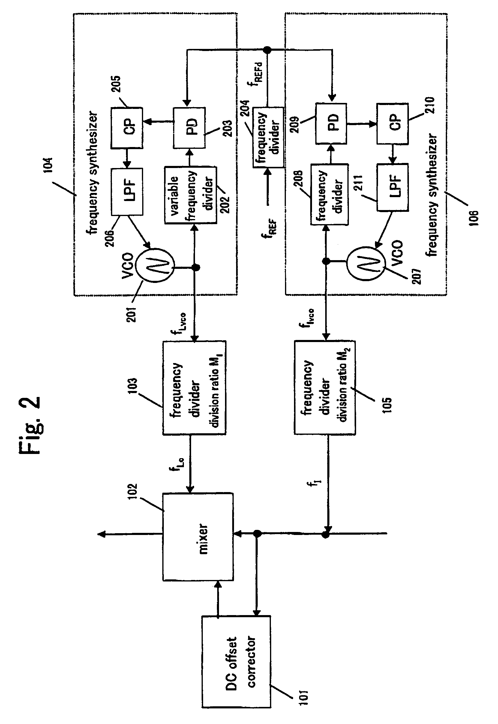
[0051]Now referring to FIG. 2, the present invention will be described. The frequency synthesizer 104 that generates the local signal fLO includes a voltage control oscillator (VCO) 201, a variable frequency divider 202 that divides the frequency of that signal, a phase comparator (PD) 203 that compares an output signal of the variable frequency divider 202 and a phase comparison reference signal fREFd so as to output a signal proportionate to the phase difference, a charge pump (CP) 205 that converts the signal from the phase comparator 205 into a current, and a low pass filter (LPF) 206 that smoothens the output signal of the charge pump 205 and outputs the smoothened signal to a control terminal of the voltage control oscillator 201 as a control signal.
[0052]Likewise, the frequency synthesizer 106 that generates the interfering signal fI includes a voltage control oscillator 207, a frequency divider 208 that divides the frequency of that signal, a phase comparator 209 that compar...
third embodiment
[0057]FIG. 3 shows a configuration of a compatible with a dual band device, according to the present invention; This DC offset calibration system includes two mixers 102, 302 to handle two different bands namely a band 1 and a band 2, and the respective mixers 102, 302 include a DC offset corrector 101, 301. The DC offset correctors 101, 301 have a similar configuration to FIG. 6. The mixers 102, 302 receive a local signal fLo, fLo2, and an interfering signal fI, fI2 respectively. The mixer 102 corresponds to the band 1, and the mixer 302 corresponds to the band 1.
[0058]A feature of the third aspect of the present invention is that a frequency synthesizer 306 that generates fI and fI2 as an interfering signal does not have a frequency switching function. In other words, the frequency synthesizer 306 is the same as the frequency synthesizer 106 in FIG. 2, but with a fixed frequency divider 305 instead of the frequency divider 208. Also, frequency dividers 303, 304 are employed in pla...
PUM
 Abstract
Description
Claims
Application Information
 - R&D
- Intellectual Property
- Life Sciences
- Materials
- Tech Scout
- Unparalleled Data Quality
- Higher Quality Content
- 60% Fewer Hallucinations
Browse by: Latest US Patents, China's latest patents, Technical Efficacy Thesaurus, Application Domain, Technology Topic, Popular Technical Reports.
© 2025 PatSnap. All rights reserved.Legal|Privacy policy|Modern Slavery Act Transparency Statement|Sitemap|About US| Contact US: help@patsnap.com


