Dual plasma beam sources and method

a plasma beam and beam source technology, applied in the field of plasma and ion generation methods and apparatuses, can solve the problems of difficult linear extension of point electron source technologies such as filaments, heated low work function materials and hollow cathodes, and ineffective processing of wide substrate applications,

Inactive Publication Date: 2008-08-12
GENERAL PLASMA
View PDF36 Cites 434 Cited by
  • Summary
  • Abstract
  • Description
  • Claims
  • Application Information

AI Technical Summary

Problems solved by technology

While successfully applied to small substrate applications like semiconductors or optical filters, they are less effective in processing wide substrate applications.
Point electron source technologies such as filaments, heated low work function materials and hollow cathodes are difficult to linearly extend.
Consequently, the ion and plasma sources that rely on these point electron sources have difficulty producing the uniform linear beams required for large area substrates.
In the case of anode layer ion sources, while a uniform ion beam is emitted over a long source length, these sources suffer from lack of ion density and the beam can be difficult to neutralize for long sources.
The result is that while useful coatings may be deposited on the substrate, the source is quickly coated causing process drift and arcing.
In these applications an etch cleaning cycle is not practical.
Unbalanced Magnetron Sources

Method used


Image

  • Dual plasma beam sources and method
  • Dual plasma beam sources and method
  • Dual plasma beam sources and method

Examples


Embodiment Construction

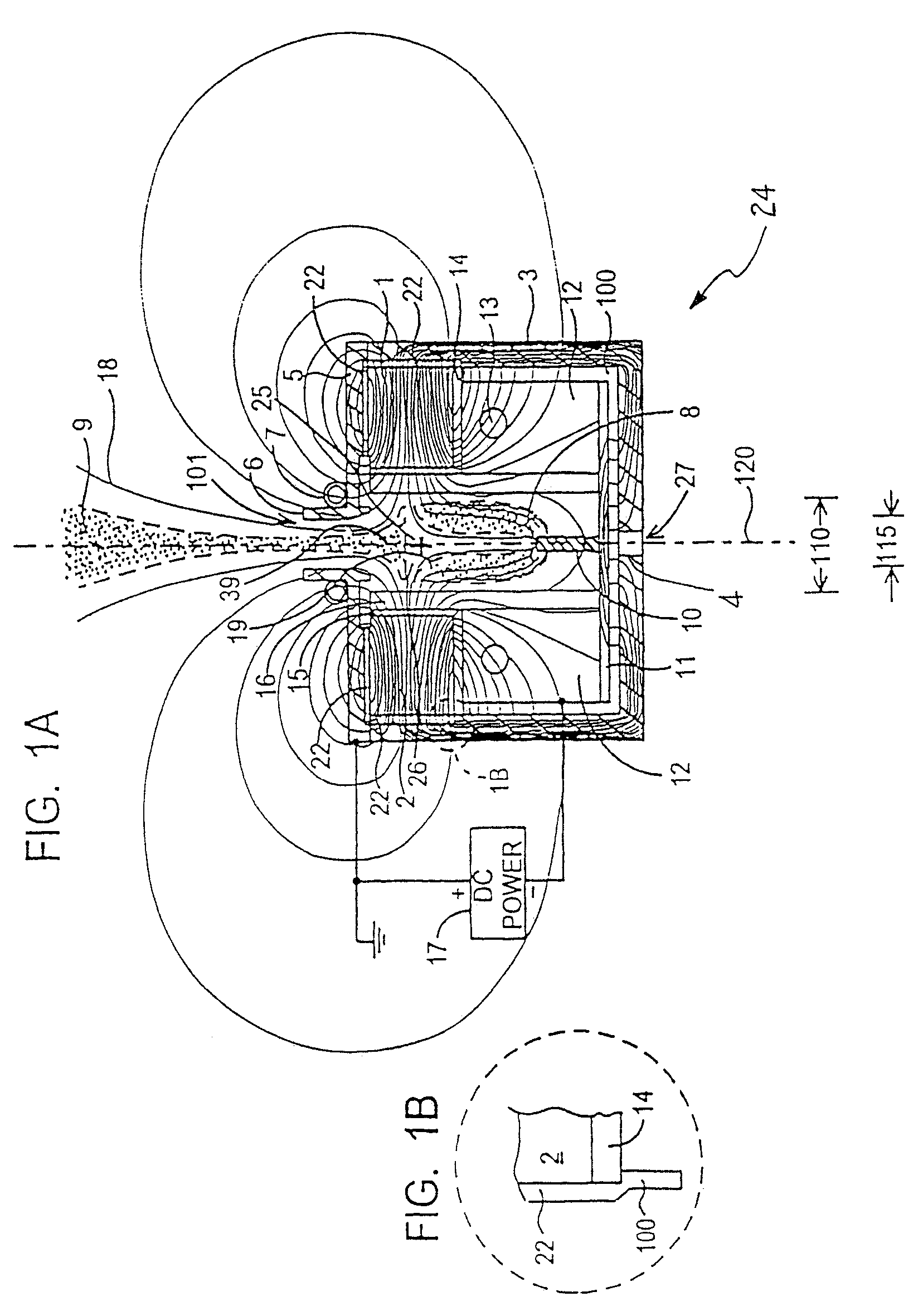
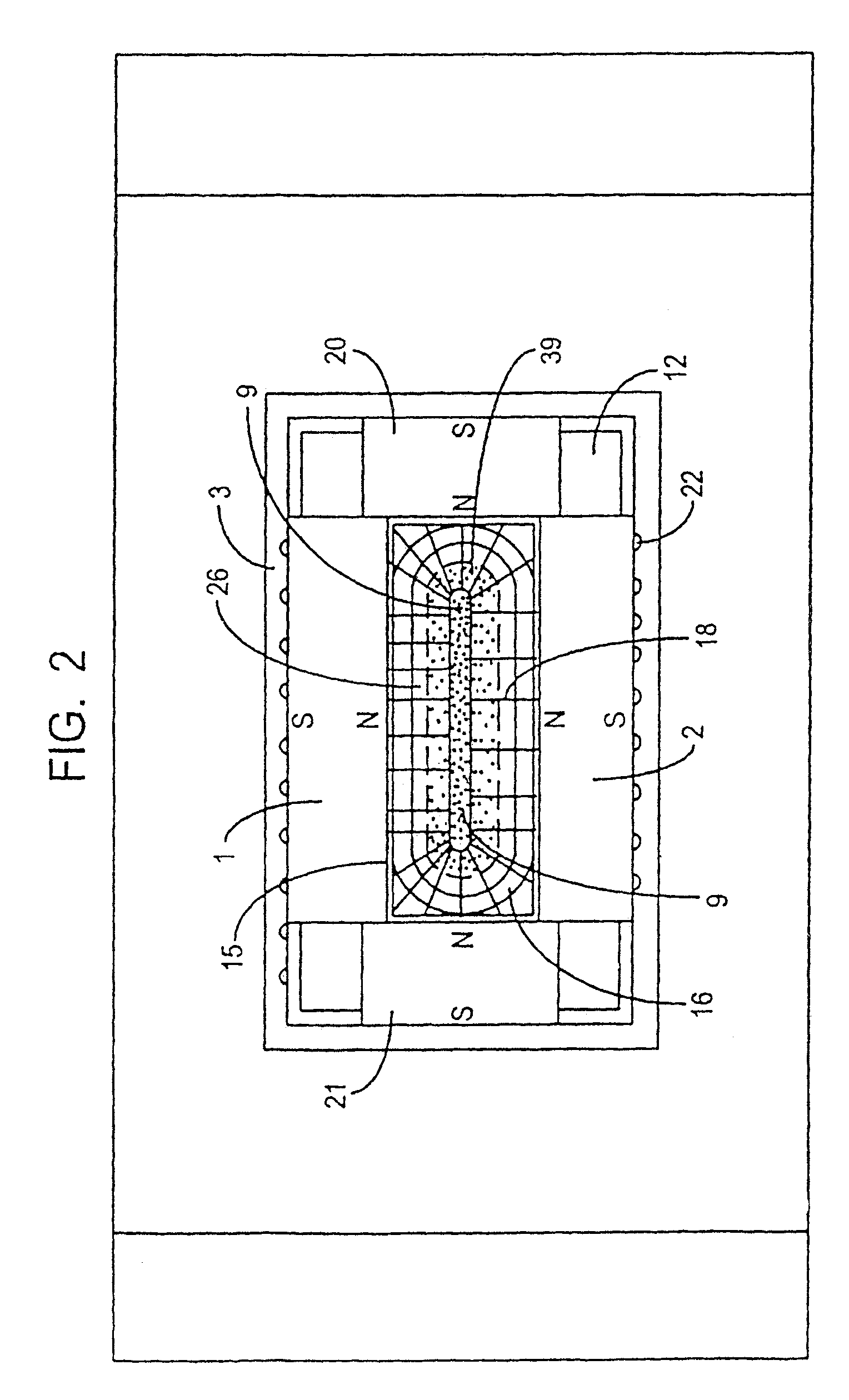
[0044]FIG. 1A shows a section view of a plasma beam source 24 producing a beam of dense plasma 9 projecting from a nozzle 6. The source resides in a process chamber, not shown, at a reduced pressure. Magnets 1 and 2 are disposed facing each other with the south poles supported by magnetic steel shunt box 3. The magnets 1 and 2 produce a cusp magnetic field composed of outwardly directed field lines 18 and inwardly directed lines 19. Inwardly directed lines 19 pass through insulator 15 and liner 16 to center shunt 10. The cusp magnetic field creates a null magnetic field region 25 inside discharge cavity 26. Magnets 1 and 2 and end magnets 20 and 21 (see FIG. 2) create endless electron traps in plasma regions 9 and 8. Shunt 10 is connected to shunt 11, and both are made of magnetic steel. Liner 16 is brazed to block 12 to improve heat transfer. Block 12 is water cooled via gun drilled holes 13 and piping (not shown). Shunt 11 is fastened to block 12. The assembly of liner 16, block 1...


PUM

PropertyMeasurementUnit
ion saturation currentaaaaaaaaaa
widthsaaaaaaaaaa
pressuresaaaaaaaaaa

Abstract

A pair of plasma beam sources are connected across an AC power supply to alternatively produce an ion beam for depositing material on a substrate transported past the ion beams. Each plasma beam source includes a discharge cavity having a first width and a nozzle extending outwardly therefrom to emit the ion beam. The aperture or outlet of the nozzle has a second width, which second width is less than the first width. An ionizable gas is introduced to the discharge cavity. At least one electrode connected to the AC power supply, alternatively serving as an anode or a cathode, is capable of supporting at least one magnetron discharge region within the discharge cavity when serving as a cathode electrode. A plurality of magnets generally facing one another, are disposed adjacent each discharge cavity to create a magnetic field null region within the discharge cavity.

Description

CROSS REFERENCE TO RELATED APPLICATION[0001]The present application is a continuation-in-part application of co-pending U.S. application Ser. No. 10 / 528,386, filed Mar. 17, 2005. This application also claims priority from PCT Application No. PCT / US03 / 29204, filed Sep. 19, 2003 and U.S. Provisional Patent Application Ser. No. 60 / 412,051, filed Sep. 19, 2002.BACKGROUND OF THE INVENTION[0002]1. Field of the Invention[0003]The present invention relates generally to methods and apparatus for generating plasma and ion and to the use thereof. The invention has particular utility with respect to plasma and ion sources used for industrial processes such as plasma treatment, plasma enhanced chemical vapor deposition (PECVD) and plasma etching of substrates and will be described in connection with such utility, although other utilities are contemplated such as for use as electric propulsion devices for space applications.[0004]2. Description of Related Art[0005]Plasma and ion sources are usefu...

Claims


Application Information

Patent Timeline
Patent Type & Authority Patents(United States)
IPC IPC(8): H01J7/24
CPCC23C14/32H05H1/46H01J37/3266C23C16/513H01L21/3065H05H1/24H05H1/30
Inventor MADOCKS, JOHN E.
Owner GENERAL PLASMA
Why Eureka
Try Eureka