Anode electrodes for direct oxidation fuel cells and systems operating with concentrated liquid fuel

a fuel cell and direct oxidation technology, applied in the field of electrodes/electrode assemblies for direct oxidation fuel cells and dofc systems, can solve the problems of parasitic power loss, methanol partly permeates the membrane electrolyte, and reducing the system energy density,

Inactive Publication Date: 2008-08-19
PANASONIC CORP +1
View PDF14 Cites 9 Cited by
  • Summary
  • Abstract
  • Description
  • Claims
  • Application Information

AI Technical Summary

Benefits of technology

[0002]DOFC is an electrochemical device that generates electricity from electrochemical oxidation of a liquid fuel. DOFC's do not require a preliminary fuel processing stage; hence, they offer considerable weight and space advantages over indirect fuel cells, i.e., cells requiring preliminary fuel processing. Liquid fuels of interest for use in DOFC's include methanol, formic acid, dimethyl ether, etc., and their aqueous solutions. The oxidant may be substantially pure oxygen or a dilute stream of oxygen, such as that in air. Significant advantages of employing a DOFC in portable and mobile applications (e.g., notebook computers, mobile phones, personal data assistants, etc.) include easy storage / handling and high energy density of the liquid fuel.
[0009]The second approach is a passive water return technique in which hydraulic pressure at the cathode is generated by including a highly hydrophobic microporous layer (hereinafter “MPL”) in the cathode, and this pressure is utilized for driving water from the cathode to the anode through a thin membrane (Ren et al. and Pasaogullari & Wang, J. Electrochem. Soc., pp A399-A406, March 2004). While this passive approach is efficient and does not incur parasitic power loss, the amount of water returned, and hence the concentration of methanol fuel, depends strongly on the cell temperature and power density. Presently, direct use of neat methanol is demonstrated only at or below 40° C. and at low power density (less than 30 mW / cm2). Considerably less concentrated methanol fuel is utilized in high power density (e.g., 60 mW / cm2) systems at elevated temperatures, such as 60° C. In addition, the requirement for thin membranes in this method sacrifices fuel efficiency and operating cell voltage, thus resulting in lower total energy efficiency.
[0011]Accordingly, there is a prevailing need for DOFC / DMFC systems that maintain a balance of water in the fuel cell and return a sufficient amount of water from the cathode to the anode when operated with highly concentrated fuel and low oxidant stoichiometry ratio, i.e., less than about 8, such as about 2. There is an additional need for DOFC / DMFC systems that operate with highly concentrated fuel, including neat methanol, and minimize the need for external water supplies or condensation of electrochemically produced water.
[0014]Another advantage of the present disclosure is improved anode electrodes for use in DOFC's operating with concentrated liquid fuel, such as methanol.
[0015]Still another advantage of the present disclosure is improved anode electrodes of simplified structure and suitable for use in fuel cells.

Problems solved by technology

One drawback of a conventional DMFC is that the methanol partly permeates the membrane electrolyte from the anode to the cathode, such permeated methanol being termed “crossover methanol”.
However, the problem with such a DMFC system is that it requires a significant amount of water to be carried in a portable system, thus diminishing the system energy density.
While this method achieves the goal of carrying concentrated (and even neat) methanol in the fuel cartridge, it suffers from a significant increase in system volume and parasitic power loss due to the need for a bulky condenser and its cooling / pumping accessories.
Considerably less concentrated methanol fuel is utilized in high power density (e.g., 60 mW / cm2) systems at elevated temperatures, such as 60° C. In addition, the requirement for thin membranes in this method sacrifices fuel efficiency and operating cell voltage, thus resulting in lower total energy efficiency.

Method used


Image

  • Anode electrodes for direct oxidation fuel cells and systems operating with concentrated liquid fuel
  • Anode electrodes for direct oxidation fuel cells and systems operating with concentrated liquid fuel
  • Anode electrodes for direct oxidation fuel cells and systems operating with concentrated liquid fuel

Examples


Embodiment Construction

[0047]The present disclosure relates to high power conversion efficiency, DOFC and systems operating with highly concentrated fuel, e.g., DMFC's and DMFC systems, and electrodes / electrode assemblies therefor.

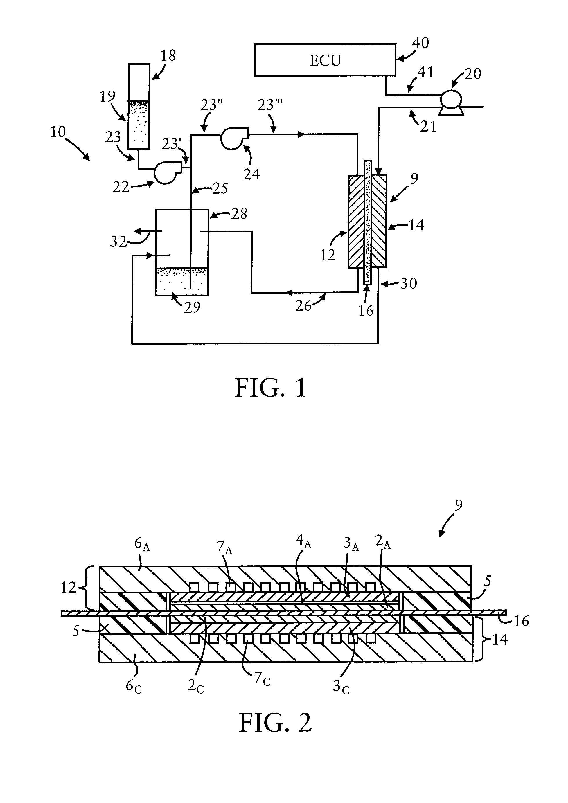
[0048]Referring to FIG. 1, schematically shown therein is an illustrative embodiment of a DOFC system adapted for operating with highly concentrated fuel, e.g., a methanol-based DMFC system 10, which system maintains a balance of water in the fuel cell and returns a sufficient amount of water from the cathode to the anode under high-power and elevated temperature operating conditions. (A DOFC / DMFC system is disclosed in co-pending, commonly assigned U.S. patent application Ser. No. 11 / 020,306, filed Dec. 27, 2004).

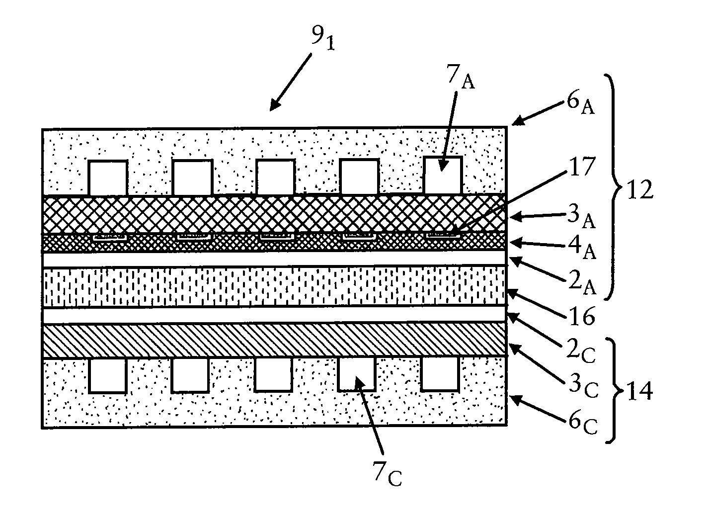
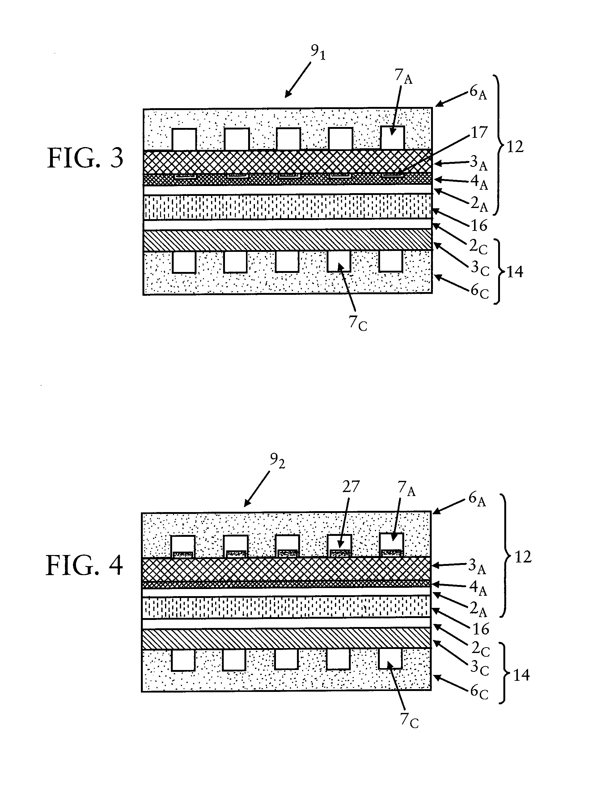
[0049]As shown in FIG. 1, DMFC system 10 includes an anode 12, a cathode 14, and a proton-conducting electrolyte membrane 16, forming a multi-layered composite MEA 9. Typically, a fuel cell system such as DMFC system 10 will have a plurality of such MEA's in the form o...


PUM

PropertyMeasurementUnit
temperaturesaaaaaaaaaa
thicknessaaaaaaaaaa
temperatureaaaaaaaaaa

Abstract

An anode electrode for use in a fuel cell comprises a stacked structure including, in sequence: a catalyst layer, a hydrophobic, microporous layer (“MPL”), a porous gas diffusion layer (“GDL”), and an anode plate with at least one recessed fuel supply-fuel / gas exhaust channel formed in a surface thereof facing the GDL, wherein the stacked structure further comprises at least one hydrophobic region aligned with the at least one recessed channel. The electrode is useful in direct oxidation fuel cells and systems, such as direct methanol fuel cells operating with highly concentrated liquid fuel.

Description

FIELD OF THE INVENTION[0001]The present disclosure relates generally to fuel cells, fuel cell systems, and electrodes / electrode assemblies for same. More specifically, the present disclosure relates to anodes for direct oxidation fuel cells (“DOFC”) and DOFC systems, such as direct methanol fuel cells (“DMFC”) and DMFC systems.GROUND OF THE DISCLOSURE[0002]DOFC is an electrochemical device that generates electricity from electrochemical oxidation of a liquid fuel. DOFC's do not require a preliminary fuel processing stage; hence, they offer considerable weight and space advantages over indirect fuel cells, i.e., cells requiring preliminary fuel processing. Liquid fuels of interest for use in DOFC's include methanol, formic acid, dimethyl ether, etc., and their aqueous solutions. The oxidant may be substantially pure oxygen or a dilute stream of oxygen, such as that in air. Significant advantages of employing a DOFC in portable and mobile applications (e.g., notebook computers, mobile...

Claims


Application Information

Patent Timeline
Patent Type & Authority Patents(United States)
IPC IPC(8): H01M2/14H01M2/00H01M2/02H01M4/00
CPCH01M4/8605H01M4/8636H01M4/8657H01M8/0245H01M8/0258H01M8/0243H01M8/0234H01M8/0239Y02E60/50H01M8/04291H01M8/1009Y02E60/523H01M8/0263H01M8/0265
Inventor UEDA, HIDEYUKIWANG, CHAO-YANG
Owner PANASONIC CORP
Why Eureka
Try Eureka