
Method and device for controlling operational processes, especially in a vehicle

a technology for operating processes and vehicles, applied in the field of vehicles, can solve problems such as inability to forward data cannot be transmitted erroneous functional units are not able to forward potentially faulty or undesired data via the bus system, so as to improve the safety of an integrated network and increase computational performan

Inactive Publication Date: 2008-08-26
ROBERT BOSCH GMBH
View PDF9 Cites 4 Cited by
  • Summary
  • Abstract
  • Description
  • Claims
  • Application Information

AI Technical Summary

Benefits of technology

[0013]According to one example embodiment of the present invention, it is provided that the functional unit is in contact with several bus systems and that the error signal is applied to connecting units of several of the bus systems. The advantage of the present invention, that the forwarding of data by an erroneous functional unit is able to be prevented safely and reliably without the use of additional hardware, such as, for instance, additional switching elements for interrupting the connection between erroneous functional unit and bus system, is especially useful when the erroneous functional unit is in contact not only with one but with several bus systems, via which data are able to be sent to other functional units. In all bus systems that are connected to the erroneous functional unit and which are to be deactivated in case of an error, the error signal of the monitoring unit is conducted to the connecting units. Bus systems which are only used for transmitting data of non-safety-relevant operational sequences (e.g., of comfort functions), do not necessarily have to be switched off in case of an error of the functional unit.
[0014]Furthermore, according to an example embodiment of the present invention, it is provided that the error signal be applied at the outputs of components whose operational sequences are controlled or regulated by the erroneous functional unit. These components are, for example, outputs of the ignition, the fuel injection and / or the throttle valve of an internal combustion engine. The aim of this measure is to bring the internal combustion engine safely to a stop, in case of an error in the controlling or regulating functional unit.
[0015]It may be advantageous that, after the detection of an error of the functional unit, the functional unit continues to be monitored by the monitoring unit, and the at least one connecting unit is activated again in case a proper function of the functional unit is detected. This renewed activation of the connecting units is possible at any time in the present invention. In contrast, in the prior art, in which, in case of an error, a reset of the erroneous functional unit is executed, a proper functioning of the functional unit could only be detected subsequent to the reset and the running up of the functional unit. Consequently, using the present invention, one may improve not only the safety of an integrated network which includes several functional units that are in contact with one another via a bus system, but also the availability of the integrated network, since the proper functioning of a functional unit may be detected particularly rapidly.
[0016]The monitoring unit has means for forming and emitting an error signal which assumes different values as a function of whether or not the monitoring unit has detected an error of the functional unit, and that the error signal is conducted to the at least one connecting unit and that the at least one connecting unit should be able to be deactivated by the error signal that is present, if the error of the functional unit was detected. The device corresponds, for example, to an integrated network that includes several functional units which are in contact with one another via a bus system.
[0017]According to one embodiment of the present invention, it is provided that the error signal is applied to an enable / disable input of the at least one connecting unit. Alternatively, it is provided that the error signal be conducted to a reset input of the at least one connecting unit.
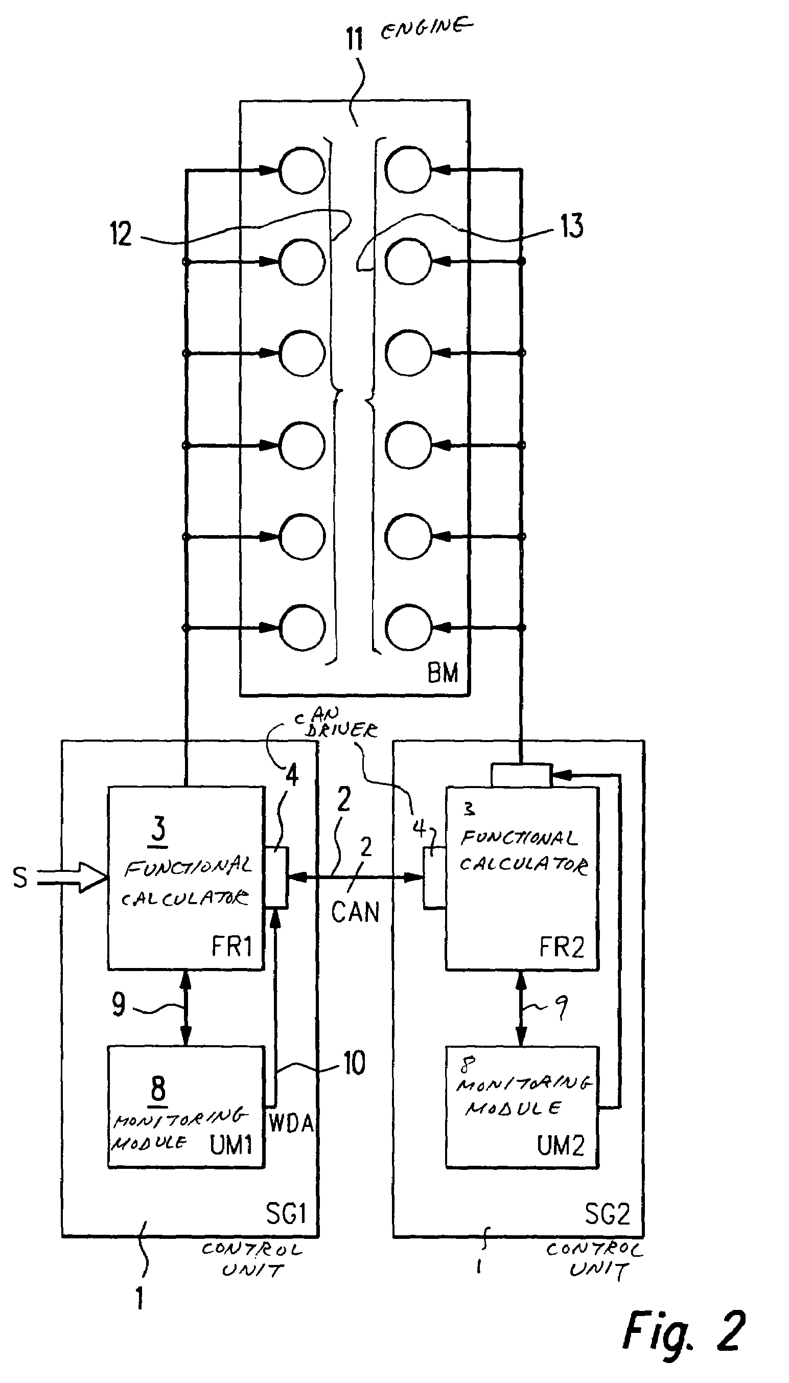
[0018]The device advantageously includes several functional units which are connected to one another via a bus system, and at least one monitoring unit, the monitoring unit preventing the forwarding of data by a functional unit via the at least one bus system, in case the monitoring unit has detected an error of this functional unit. Such a device corresponds to the so-called multi-control unit concept that has increasingly been used in motor vehicles recently, in which several control units are put in in parallel to one another to increase computational performance, the individual control units each controlling a certain part of the operational sequences. Thus, for example, in a two-control unit concept for controlling an 8-cylinder internal combustion engine, a first control unit is put in for controlling four of the cylinders and a second control unit for controlling the remaining four cylinders. The two control units are in contact with each other via a bus system. Data concerning the operational state of the internal combustion engine or of the motor vehicle are only supplied to the first control unit, which then passes the data on to the second control unit via the bus system. If the monitoring unit of the first control unit detects an error of the control unit, it deactivates the connecting unit of the bus system to the second control unit, so as to prevent the first control unit from forwarding erroneous data to the second control unit and having the second control unit controlling the remaining four cylinders of the internal combustion engine in a faulty manner and even possibly having a safety-relevant situation coming about.

Problems solved by technology

Here too, it has proven problematical that likewise separate switching elements have to be provided in the connection between the functional unit and the bus system, so that the functional unit is able to be decoupled from the bus system in the error case.
Thus, in the known method, a faulty functional unit may possibly forward faulty data via the bus system, even though the monitoring unit has detected an error of the functional unit.
However, these data are no longer able to be transmitted via the bus system, since the connecting unit required for the forwarding of data has been deactivated.
Consequently, in the error case, an erroneous functional unit is not able to forward any potentially faulty or undesired data via the bus system.
To the extent that the errors of the functional unit permit it, the latter still works quite normally, i.e., it still generates data for controlling and / or regulating the operational sequences, these data, however, possibly being erroneous.
However, these data are not able to be transmitted via the bus system.
The reason for the need to prevent the forwarding of data by the functional unit in the error case is that an erroneous functional unit may no longer have control over itself and over the correct generation of data to be sent, and because of its own error it is also not able to switch itself off reliably and safely.
Because of a defective functional unit in an integrated network, in which several functional units are in contact with one another via a bus system, there is a danger that the remaining receiving functional units on the bus system may receive erroneous data from the erroneously forwarding functional unit, and thus prompted, carry out unwanted actions.
Taking the example of motor vehicle control units, a control unit for the internal combustion engine could, in the error case, for example, cause a transmission control unit to shift down into lower gears, whereby the vehicle could arrive at an unstable travel state.

Method used


Image

  • Method and device for controlling operational processes, especially in a vehicle
  • Method and device for controlling operational processes, especially in a vehicle
  • Method and device for controlling operational processes, especially in a vehicle

Examples


Embodiment Construction

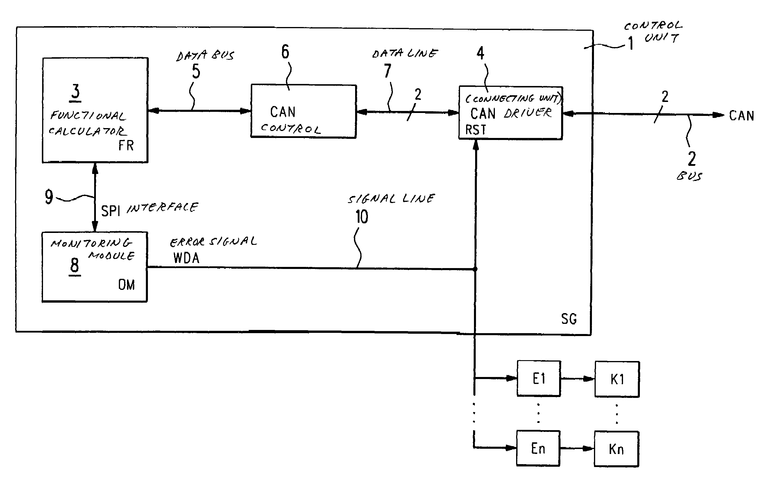
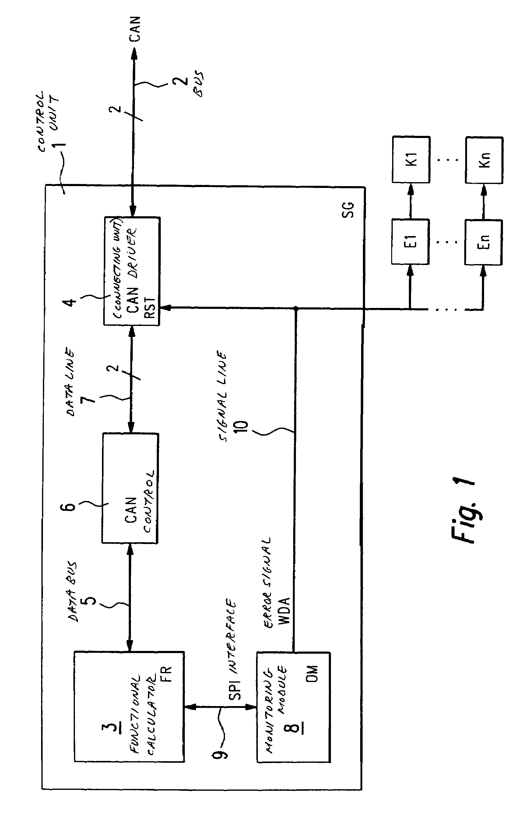
[0025]In FIG. 1, a control unit SG according to the present invention is designated in its entirety by reference numeral 1. Control unit 1 is used, for example, for controlling and / or regulating operational sequences in a motor vehicle. Subsequently, we will go into more detail, for example, on a control unit 1 for controlling of operational sequences in an internal combustion engine of a motor vehicle. However, the present invention is generally applicable to all types of control units SG, such as for transmission control, vehicle dynamics control, drive slip control (ASR), an automatic distance control (EDC; electronic distance control), adaptive cruise control (ACC), etc, which control units are in contact with one another via a bus system 2 to an integrated control unit system, and which exchange data among one another via bus system 2. Bus system 2 is, for instance, developed as a CAN (controller area network).

[0026]Control unit 1 includes a functional calculator FR 3 which is ...


PUM


Abstract

The present invention provides a method and a device for controlling operational sequences, in particular in a vehicle. In this context, a functional unit for forwarding and receiving data via at least one connecting unit is in contact with at least one bus system. Functional unit is monitored by a monitoring unit. The monitoring unit prevents the forwarding of data by the functional unit via the at least one bus system if the monitoring unit detects an error of the functional unit. In an error case, in order to prevent the forwarding of data by functional unit in a manner as simple as possible, yet one that is safe and reliable, an error signal is emitted by the monitoring unit, which error signal assumes different values as a function of whether an error of the functional unit has been recognized or not, and the error signal is applied to the at least one connecting unit such that the at least one connecting unit is deactivated by the error signal if an error of the functional unit has been detected.

Description

FIELD OF THE INVENTION[0001]The present invention relates to a device and a method for controlling and / or regulating operational sequences, particularly in a motor vehicle, in which a functional unit for forwarding and receiving data via at least one connecting unit is in contact with at least one bus system.BACKGROUND INFORMATION[0002]A circuit configuration for decoupling an electronic device from a data line in a motor vehicle is described, e.g., in published German patent document DE 198 33 462. The electronic device and at least one additional electrical system exchange data via the data line, during the operation of the electronic device. In the case of the circuit configuration where vehicle operation can be maintained despite a malfunction of an electronic device connected to the data line, the electronic device is connected to a fault detection device. In response to the fault detection device ascertaining a fault of the electronic device, the electronic device is decoupled...

Claims


Application Information

Patent Timeline
Patent Type & Authority Patents(United States)
IPC IPC(8): G05B19/418G06F19/00B60R16/02B60R16/023G05B9/02H04L12/40
CPCG05B9/02H04L12/40H04L12/4135H04L12/40032H04L2012/40273H04L2012/40215G05B19/418
Inventor PFEUFER, REINHARDMUELLER, MARGITHAAG, WOLFGANGKELLER, STEFAN
Owner ROBERT BOSCH GMBH
Learn More