Systems and methods for creating stable camera optics

a camera optics and system technology, applied in the field of imaging systems, can solve the problems of compromising the optics, losing the reflectivity of conventional reflective materials, and silicone-based materials having drawbacks that compromise the optics, and the materials are typically very difficult to work

Active Publication Date: 2008-09-02
SIEMENS MEDICAL SOLUTIONS USA INC
View PDF13 Cites 5 Cited by
  • Summary
  • Abstract
  • Description
  • Claims
  • Application Information

AI Technical Summary

Benefits of technology

[0014]The preferred embodiments of the present invention can significantly improve upon existing methods and / or apparatuses.
[0020]According to some other embodiments, a method for creating stable camera optics is performed that includes: emitting photons from a source towards a plurality of photon receivers; directing the emitted photons through an optical interface between the photon emitting source and the plurality of photon receivers, including directing the photons through a lightguide and an optical coupling gel and including reflecting photons off a light reflective coating at locations adjacent the optical coupling gel and between the photon receivers; and providing an optical coupling gel that is prone to discoloration from local contaminants, but providing the light reflective coating with a chemistry that is free of contaminants that cause discoloration of the optical coupling gel. In preferred embodiments, the method includes providing the optical coupling gel as a silicon-based coupling gel and the light reflective coating with components selected from the group consisting of alkyds, polyesters and acrylics.
[0021]According to some other preferred embodiments, a medical imaging system having stable camera optics is provided that includes: a photon emitting source that emits photons towards a plurality of photon receivers; an optical interface between the photon emitting source and the plurality of photon receivers including an optical coupling gel that is prone to discoloration from local contaminants and an optical coating adjacent the optical coupling gel; the optical coating having means for avoiding discoloration of the optical coupling gel.

Problems solved by technology

Conventional reflective materials, such as porous teflon, lose their reflectivity in these situations.
However, silicone-based materials have drawbacks that compromise the optics.
These materials are typically very difficult to work with.
They tend to migrate away from the area(s) where they are needed, and they tend to pick up contaminants and to discolor.
Despite the drawbacks that these greases tend to pick up contaminants from the local environment and to discolor because of the absorbed contaminants, most gamma cameras use a silicone-based optical grease.
Another drawback of these greases is that they also require extensive mechanical devices in order to hold the PMTs in the grease.
In addition, these greases need to be replaced in the field relatively frequently (such as, e.g., about every 2-5 years) because of discoloration, which discoloration leads to signal degradation and to poor gamma camera performance.
Accordingly, this discoloration causes the need for costly and time consuming on-site repairs.
Most grease-based gamma cameras require a complete rebuild of its optics every 2-5 years due to these problems.
As should be appreciated, this creates a significant amount of downtime for the facilities using these devices, which can be not only very time consuming, but very costly.
However, the present inventors have discovered that these silicone gels are still rather prone to discolor because of interactions of the platinum catalyst typically used in these gels with local contaminants (such as, e.g., outgassing epoxies from electronic components, coatings from parts within the gamma camera [e.g., organic coatings in contact with the gel], plasticizers from wiring inside the gamma camera and / or the like).
Thus, as with silicon greases, the discoloration of silicon gels leads to degraded optics, which similarly triggers the need for on-site repairs and actions, and in severe cases can require a complete rebuilding of the gamma camera optics.
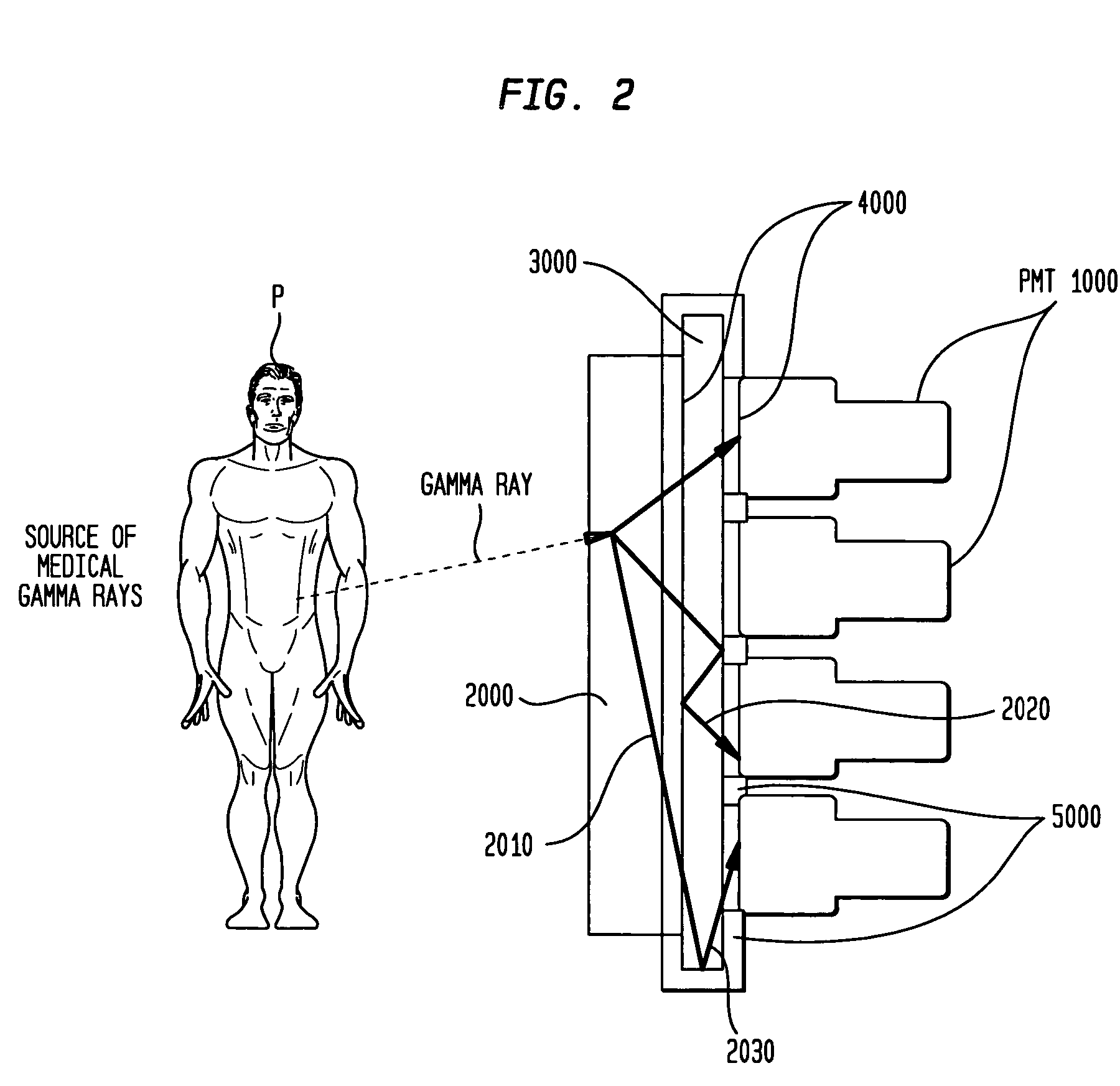
Because most PMTs have a geometry that does not allow 100% area coverage of the optical interface, some photons would be lost (e.g., in areas between the PMTs, leading to increased scan times or poorer images.

Method used


Image

  • Systems and methods for creating stable camera optics
  • Systems and methods for creating stable camera optics
  • Systems and methods for creating stable camera optics

Examples


Embodiment Construction

[0014]The preferred embodiments of the present invention can significantly improve upon existing methods and / or apparatuses.

[0015]According to some preferred embodiments of the invention, a method of inhibiting discoloration of an optical coupling for a medical imaging system is performed that includes: inhibiting an interaction between an optical coating and an optical coupling that causes discoloration of the optical coupling. Preferably, the method further includes having the medical imaging system include a nuclear medical imaging system or a PET system. In preferred embodiments, the method further includes having the optical coupling between a scintillation crystal and a photomultiplier tube and the optical coating include a light reflective coating. In addition, the method preferably further includes having the optical coupling include an optical coupling gel, and, especially, a silicon-based coupling gel, and, more especially, an optical coupling gel including a platinum cata...


PUM


Abstract

In some preferred embodiments, a medical imaging system having stable camera optics is provided that includes: a photon emitting source that emits photons towards a plurality of photon receivers; an optical interface between said photon emitting source and said plurality of photon receivers including an optical coupling gel that is prone to discoloration from local contaminants and an optical coating adjacent said optical coupling gel; and said optical coating having means for avoiding discoloration of said optical coupling gel.

Description

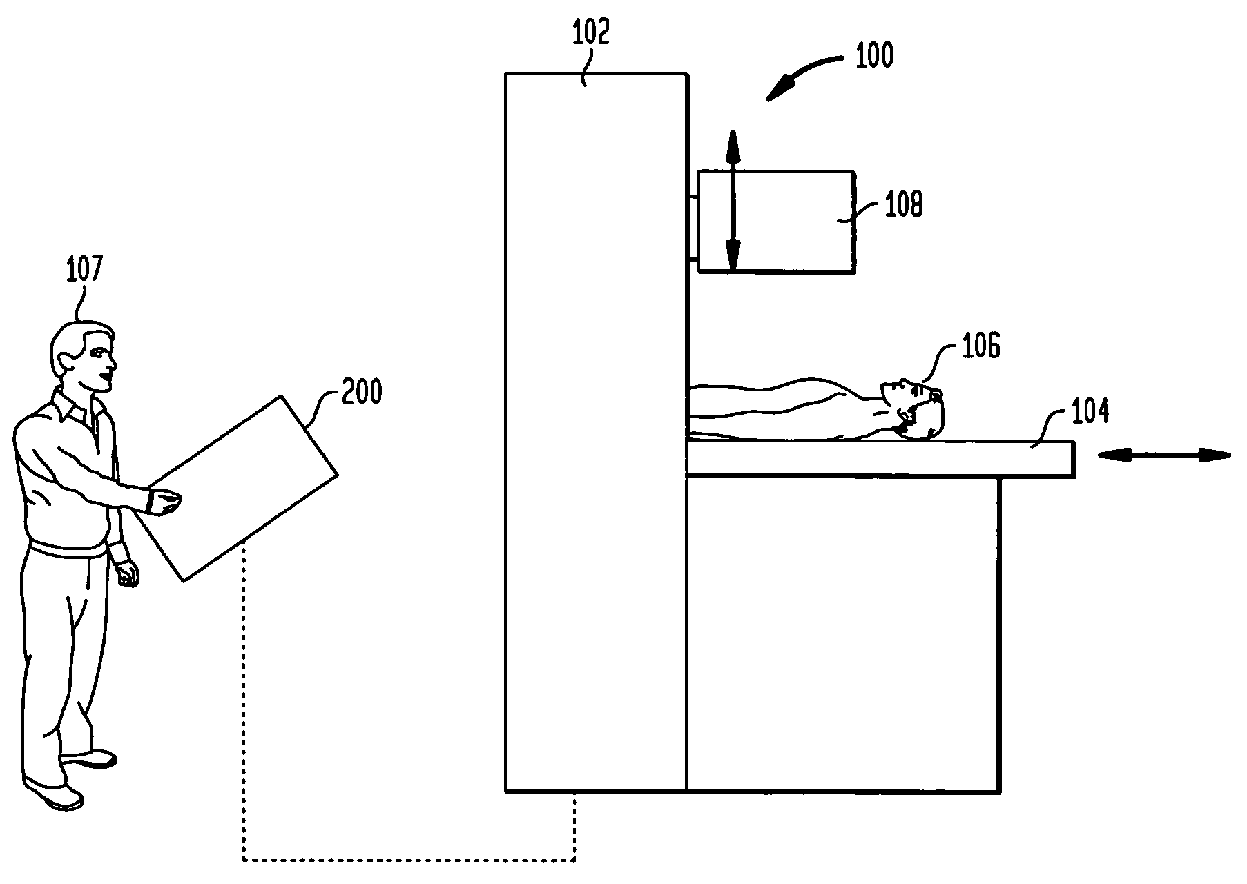
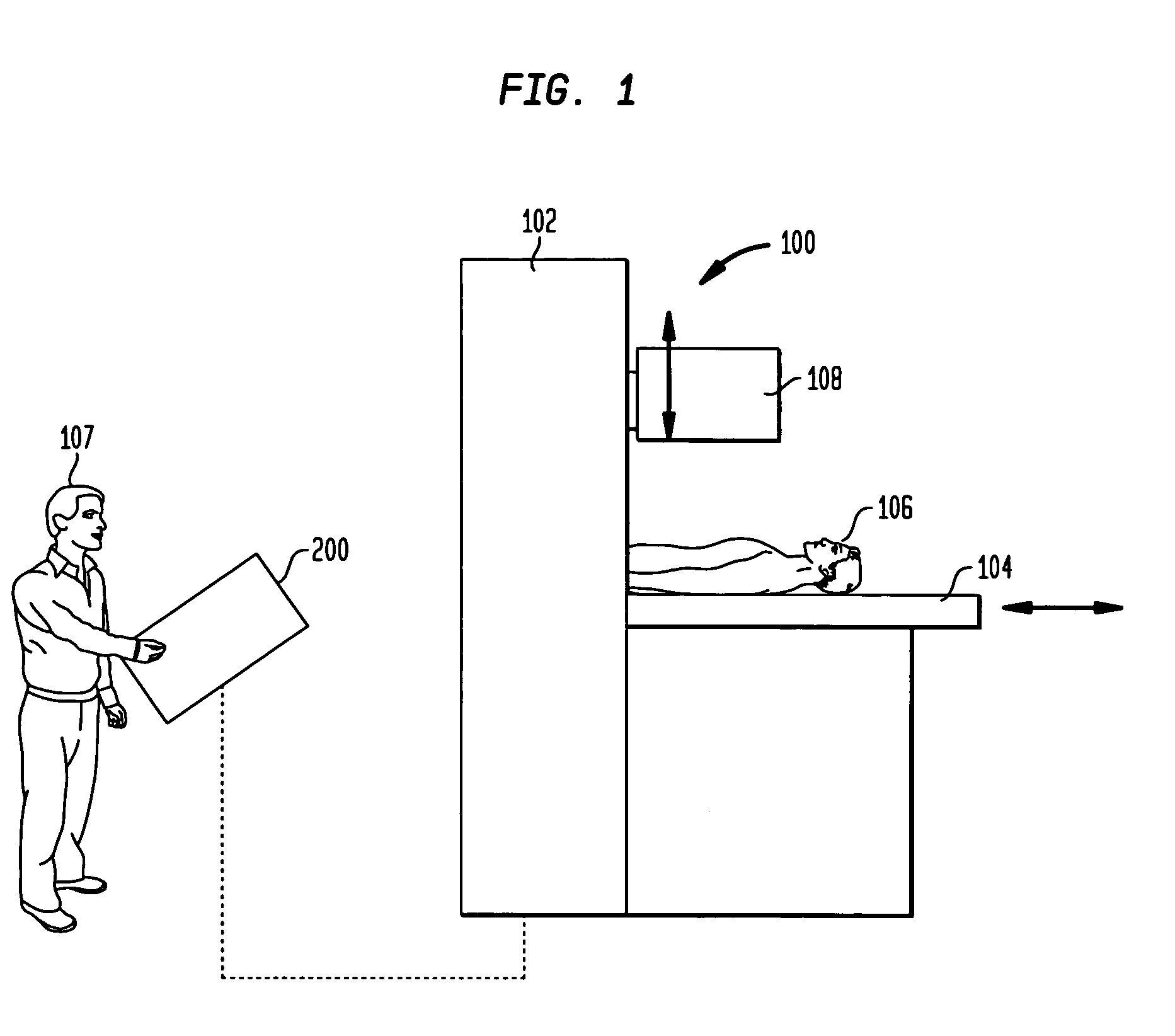
BACKGROUND[0001]1. Field of the Invention[0002]The present invention relates generally to imaging systems and, more particularly, to systems and methods for creating stable camera optics. In addition, the preferred embodiments provide a system and method for creating stable optics in medical imaging systems having optical couplings prone to discoloration by local contaminants.[0003]2. Discussion of the Background[0004]A variety of medical imaging systems are known. Some illustrative imaging systems include nuclear medical imaging systems (e.g., gamma cameras), computed tomography (CT or CAT) systems, magnetic resonance imaging (MRI) systems, positron-emission tomography (PET) systems, ultrasound systems and / or the like.[0005]With respect to nuclear medical imaging systems, nuclear medicine is a unique medical specialty wherein radiation (e.g., gamma radiation) is used to acquire images that show, e.g., the function and / or anatomy of organs, bones and / or tissues of the body. Typicall...

Claims


Application Information

Patent Timeline
Patent Type & Authority Patents(United States)
IPC IPC(8): G01D18/00
CPCG01T1/1644A61B6/4258G01T1/2002A61B6/037
Inventor WILLE, STEVEN LEWISDELMEDICO, ANTHONY P.
Owner SIEMENS MEDICAL SOLUTIONS USA INC
Why Eureka
Try Eureka