
Stretching and compression of laser pulses by means of high efficiency volume diffractive gratings with variable periods in photo-thermo-refractive glass

a technology of photothermo-refractive glass and diffractive gratings, applied in the field of diffractive optical elements, can solve the problems of fibers not being able to tolerate high power density, limited use of volume chirped gratings, and inability to model gratings with variable periods, etc., to achieve high efficiency for power amplification, broaden the spectral width, and eliminate significant beam distortions

Inactive Publication Date: 2008-09-09
RGT UNIV OF MICHIGAN +1
View PDF9 Cites 25 Cited by
  • Summary
  • Abstract
  • Description
  • Claims
  • Application Information

AI Technical Summary

Benefits of technology

[0018]The third objective of the present invention is to provide apparatus, methods, systems and devices for high power femtosecond lasers with high laser-induced damage threshold and protection from misalignment.
[0019]The fourth objective of the present invention is to provide apparatus, methods, systems and devices for increasing the power of high power femtosecond lasers while decreasing the size and weight of the laser.
[0020]The fifth objective of the present invention is to provide apparatus, methods, systems and devices for increasing the efficiency of stretching and compression to approximately 95%.
[0022]The seventh objective of the present invention is to provide apparatus, methods, systems and devices to enable creation of very large apertures with homogeneous transverse spatial profile to eliminate significant beam distortions.
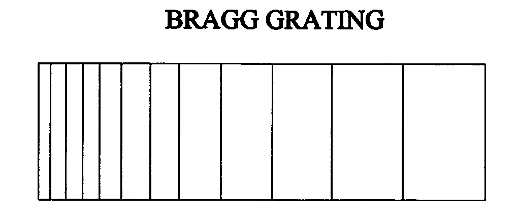
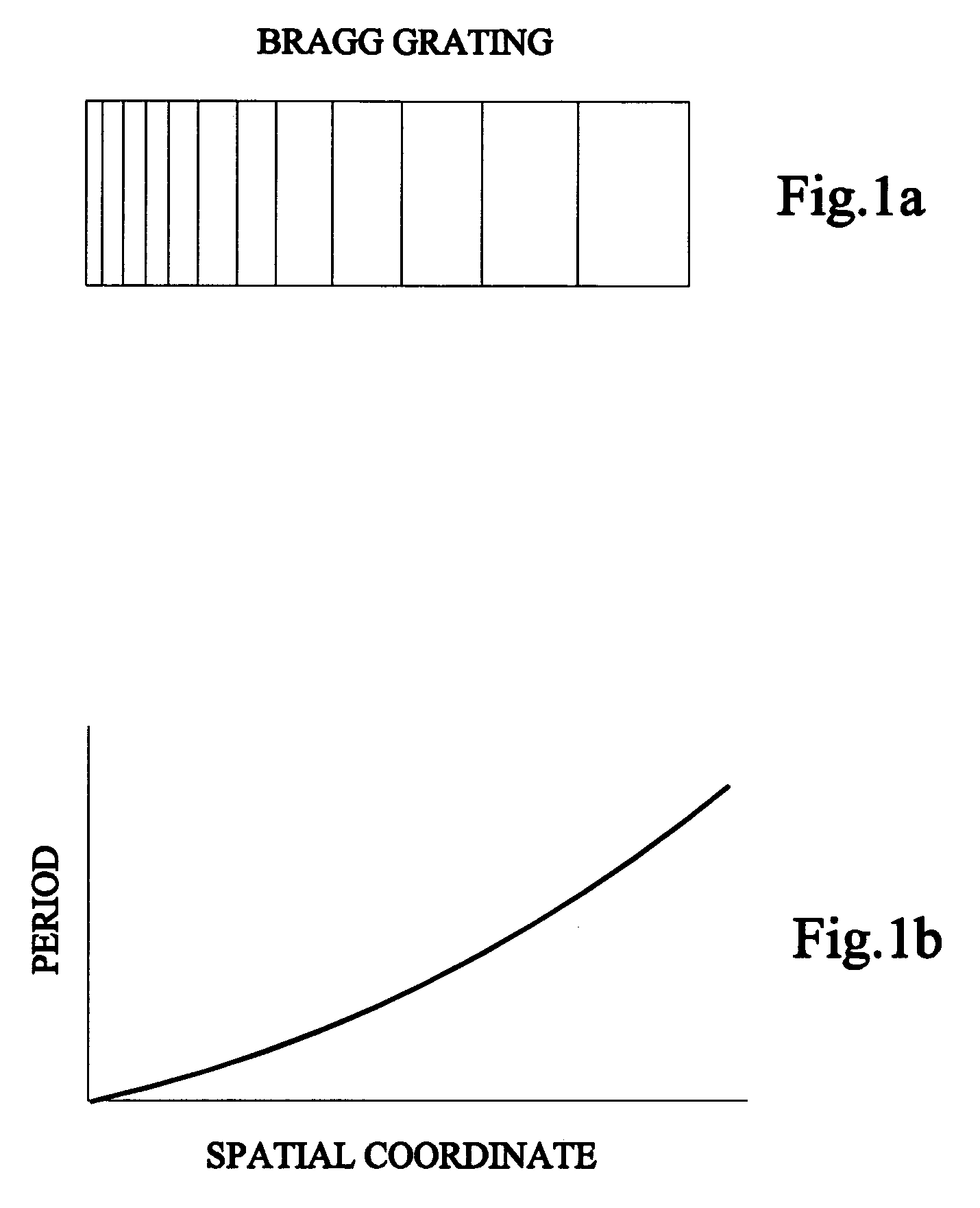
[0023]The preferred embodiment of the invention is a diffractive optical element from a photo-thermal-diffractive element having an absolute diffraction efficiency exceeding 95% with chirped Bragg gratings recorded in the photo-thermal-diffractive element for stretching and compressing of short laser pulses with high efficiency for power amplification. The chirped Bragg gratings include plural Bragg grating with a spatial chirp, the spatial chirp grating period varies along a spatial axis for broadening of spectral width and decreasing spectral selectively side lobes for fine spectral filtering. A laser beam having short laser pulses is directed from a one side to the other side of the diffractive optical element for stretching the short laser pulses. The laser beam is passed through the diffractive optical element in the opposite direction for compression of the short laser pulses. In an embodiment, the diffractive optical element is used with a femtosecond laser having ultrashort laser pulse output for stretching and compressing of the ultrashort laser pulses for power amplification with a high laser-induced damage threshold and protection from misalignment.

Problems solved by technology

The use of volume chirped gratings is restricted by the lack of available photosensitive materials which provide high sensitivity, low losses, and stability of volume in the processes of exposure and development.
It is important to note that modeling of gratings with variable period is difficult with the use of conventional Kogelnik's theory of coupled waves.
One of the drawbacks of chirped fiber gratings is that those fibers cannot tolerate high power density which is necessary for high power amplification.
This limitation is due to the small aperture resulted in high power density and, therefore, in low damage threshold of fibers.
Higher energies can only be achieved by means of a system of gratings or prisms that are added to recompress the pulses, which seriously enhance complexity of laser systems as described in C. M. Gonzalez Inchauspe, O. E. Mart nez, Aberration compensation of a curved diffraction grating stretcher for femtosecond chirped-pulse amplification.
Another disadvantage of such high requirements for alignment of surface grating and other optical elements in compression blocks like telescopes lenses, complicated mirrors that are needed as disclosed in J. Limbert, T. Schreiber, T. Clausnitzer, K. Zollner, H-J.
Small alignment errors in the positioning of all these elements can cause frequency dispersion as described in Terrance J. Kessler, Joachim Bunkenburg, Hu Huang, Alexei Kozlov, David D. Meyerhofer, Demonstration of coherent addition of multiple gratings for high-energy chirped-pulse-amplified lasers.
Moreover, those systems cannot be compact because of large distance needed between the two gratings or prisms used for compression.
A limiting factor of surface diffraction gratings is their low optical damage threshold (2 J / cm2 in 1 ns pulse) which results in very large apertures in the range of tens of centimeters.
However, manufacturing of large aperture gratings is challenging, so instead of one large coherent addition of several gratings can be used as disclosed in G. P. Agrawal, Nonlinear Fiber Optics, Academic, San Diego, Calif., 1995.
It makes such technology extremely complicated and expensive.
Another serious limitation of surface-diffraction-grating compressors is associated with the restricted average-power handling capacity.
Existing diffraction-grating compressors have not been able to tolerate more than 100-W of average power, with tens of watts being a typical limit.
With fiber laser power exceeding 1-k level, this limitation is becoming the main hindrance on the path of power scaling of ultrashort-pulse laser technology.
However, no suitable method of achieving chirped volume gratings have been identified there.
In fact, experimental attempt to implement such gratings through UV-written photosensitive-glass gratings identified main difficulty of achieving required performance as described in A. Galvanauskas, A. Heaney, T. Erdogan, D. Harter, Use of volume chirped Bragg gratings for compact high-energy chirped pulse amplification circuits, in Conference on Lasers and Electro-Optics, vol.
This, on one hand, severely limits the attainable volume-grating aperture size to no more than 100-300 um, and on the other hand, produces unacceptable beam quality loss.

Method used


Image

  • Stretching and compression of laser pulses by means of high efficiency volume diffractive gratings with variable periods in photo-thermo-refractive glass
  • Stretching and compression of laser pulses by means of high efficiency volume diffractive gratings with variable periods in photo-thermo-refractive glass
  • Stretching and compression of laser pulses by means of high efficiency volume diffractive gratings with variable periods in photo-thermo-refractive glass

Examples


Embodiment Construction

[0032]Before explaining the disclosed embodiments of the present invention in detail it is to be understood that the invention is not limited in its applications to the details of the particular arrangements shown since the invention is capable of other embodiments. Also, the terminology used herein is for the purpose of description and not of limitation.

[0033]A serious limitation of surface-diffraction-grating compressors is associated with the restricted average-power handling capacity. Existing diffraction-grating compressors have not been able to tolerate more than 100-W of average power, with tens of watts being a typical limit. With fiber laser power exceeding 1-kW level, this limitation is becoming the main hindrance on the path of power scaling of ultrashort-pulse laser technology.

[0034]Previously, a solution of reducing complexity of CPA arrangement through the use of chirped volume Bragg gratings have been proposed, in order to overcome limited mode-area of chirped fiber B...


PUM


Abstract

High efficiency reflective volume Bragg gratings with chirped gratings recorded in photo-thermo-refractive glass having an absolute diffraction efficiency exceeding 95% in transmitting and reflecting modes are used to stretch and / or compress ultrashort laser pulses with high efficiency. Robustness, compactness, thermal and laser stability along with placement of multiple elements in the same space provides femtosecond laser system with high efficiency of stretching and re-compression of femtosecond pulses.

Description

[0001]This application is a continuation-in-part of U.S. patent application Ser. No. 11 / 261,077 filed on Oct. 28, 2005 which is a continuation-in-part of U.S. patent application Ser. No. 10 / 665,339 filed on Sept. 19, 2003, now U.S. Pat. Ser. No. 7,326,500, which is a continuation-in-part of U.S. patent application Ser. No. 09 / 750,708 filed on Dec. 28, 2000, now U.S. Patent No. 6,673,497, which is a continuation-in-part of U.S. patent Ser. No. 09 / 648,293 filed on Aug. 24, 2000, now U.S. Pat. Ser. No. 6,586,141 which further claim priority from U.S. Provisional Application Ser. No. 60 / 174,432 filed Jan. 4, 2000 and which was funded by the Ballistic Missile Defense Organization Contract 66001-97-C60008 and claims the benefit of priority to U.S. Provisional Application Ser. No. 60 / 646,297 filed on Jan. 24, 2005 and was funded in part by DoD / DARPA Contract No. HR-01-1041-0004.FIELD OF THE INVENTION[0002]This invention relates to diffractive optical elements and more specifically those di...

Claims


Application Information

Patent Timeline
Patent Type & Authority Patents(United States)
IPC IPC(8): G02B6/34G03H1/04H01S3/10H01S3/30
CPCH01S3/0057G02B6/02085
Inventor GLEBOV, LEONID BFLECHER, EMILIESMIRNOV, VADIM I.GALVANAUSKAS, ALMANTASLIAO, KAI-HSIU
Owner RGT UNIV OF MICHIGAN
Learn More