Random number generator with ring oscillation circuit

a technology of ring oscillation circuit and random number generator, which is applied in the field of random number generators, can solve the problems of increasing circuit scale and complexity, mounting these elements, and being susceptible to external noise, and achieves the effect of reducing power consumption and high performan

Active Publication Date: 2008-09-09
RENESAS LSI DESIGN CORP +1
View PDF12 Cites 44 Cited by
  • Summary
  • Abstract
  • Description
  • Claims
  • Application Information

AI Technical Summary

Benefits of technology

[0009]A main object of the present invention is to provide a random number generator miniaturized and having reduced power consumption, and of high performance.
[0010]The present invention provides a random number generator including: a plurality of delay circuits connected in a loop; a pulse generation circuit generating in the loop a pulse signal having a pulse of a width shorter than a total delay time of the plurality of delay circuits; and a counter connected to an output node of a delay circuit of the plurality of delay circuits to count how many times the pulse signal passes through the output node, and output a true random number data signal based on a value counted by the counter. In the loop, a metastable state occurs having a longevity of “0”, “1” or binarized to generate true random number data. A random number generator miniaturized and having reduced power consumption, and of high performance can thus be implemented.

Problems solved by technology

Random number generators utilizing random pulses attributed to natural phenomena, however, include a random pulse generation source, a signal amplifier, a waveform shaping circuit, a uniformity optimization circuit and other similar analog elements and as a result would have increased circuit scales and also be complicated.
This is an obstacle to mounting these elements as an integrated large scale integrated circuit (LSI) on microcomputers, application specific integrated circuits (ASICs) and the like.
In addition, those utilizing thermal noise are susceptible to external noise and the like and thus operate less reliably.
Those utilizing radioactive rays may have negative effect on environments.

Method used


Image

  • Random number generator with ring oscillation circuit
  • Random number generator with ring oscillation circuit
  • Random number generator with ring oscillation circuit

Examples


first embodiment

in Exemplary Variation

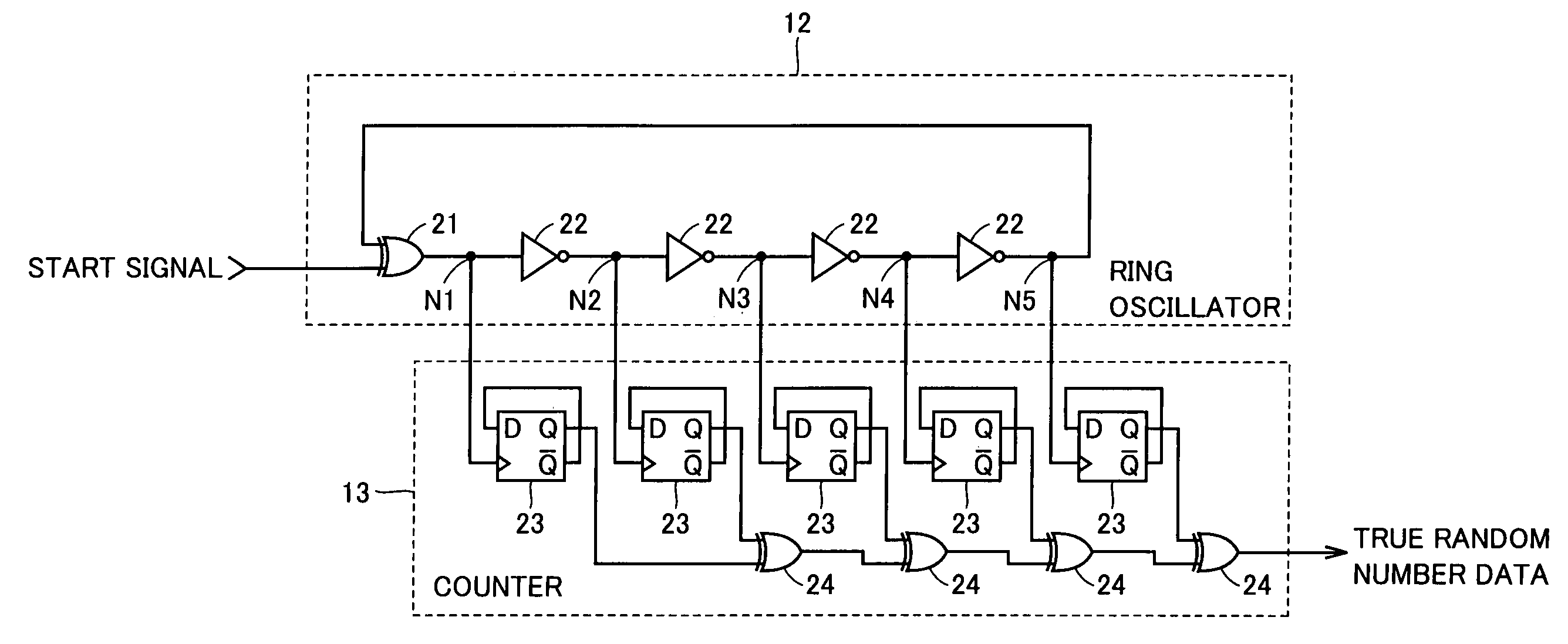
[0067]With reference to FIG. 8, the first embodiment in an exemplary variation provides ring oscillator 12 and counter 13, which are different from ring oscillator 12 and counter 13 of the first embodiment shown in FIG. 3 in that counter 13 includes flip-flop 23 reduced in number to three. In FIG. 8, flip-flop 23 is connected only to odd numbered output nodes N1, N3, N5.

[0068]In ring oscillator 12 a delay characteristic of EX-OR gate 21 causes output node N1 to tend to bias in potential toward either the high or low level. For example if a delay time introduced when EX-OR gate 21 pulls low a signal to be output therefrom is longer than that introduced when EX-OR gate 21 pulls the signal high, the EX-OR gate 21 output node N1 tends to have potential biasing toward the high level. Furthermore, because of a delay characteristic of each inverter 22, metastable state tends to disappear more often at either the odd-numbered output nodes N1, N3, N5 or even-numbered ou...

second embodiment

[0072]With reference to FIG. 9, a second embodiment provides a ring oscillator 50 and counter 13, which are different from ring oscillator 12 and counter 13 of the first embodiment shown in FIG. 3 in that EX-OR gate 21 is replaced with an NAND gate 51.

[0073]FIGS. 10A-10C are timing plots, respectively, for illustrating ring oscillator 50 and counter 13 in operation. The figures represent the start signal in three patterns for generating metastable state at output nodes N1-N5.

[0074]In FIG. 10A the start signal is a pulse signal pulled high at a time t0 and pulled low when a period of time T0 elapses. The period of time T0 (the pulse's width) is set to be shorter than a delay time T1 of the loop of ring oscillator 50. In an initial state when output nodes N1, N3, N5 have a stable state in potential of the high level and output nodes N2, N4 have a stable state in potential of the low level, output node N1 has a potential having a pulsed waveform corresponding to a delay of the start si...

third embodiment

in Exemplary Variation

[0086]With reference to FIG. 12, the third embodiment in an exemplary variation provides a ring oscillator 70 including three inverters 22 and three inverters 71, an inverter 72, and NAND gates 73-75. The FIG. 12 ring oscillator 70 corresponds to the FIG. 11 ring oscillator 60 with switch circuit SW1 implemented by NAND gates 73-75 and inverter 72. More specifically, NAND gates 73-75 and inverter 72 switches between a loop formed of an odd number of inverters and a loop formed of an even-number of inverters.

[0087]In ring oscillator 70 three inverters 22 are connected between output nodes N21 and N24 in series and three inverters 71 are connected between output nodes 24 and 25 in series. NAND gate 73 has one input terminal connected to output node N24 and the other input terminal receiving a start signal. NAND gate 74 has one input terminal connected to output node N25 and the other input terminal receiving the start signal via inverter 72. NAND gate 75 has one ...


PUM


Abstract

A random number generator includes a ring oscillator having an EX-OR gate and four inverters together forming a loop. This loop enters stable state for a start signal having the low level and oscillates for the start signal having the high level. When the start signal has a pulse of a width shorter than the loop's delay time, output nodes responsively, sequentially enter metastable state hovering between the high and low levels. The metastable waveform becomes smaller with time and finally disappears. As metastable state cannot be controlled in longevity, it disappears at any random number node. A counter thus outputs a signal serving as true random number data depending on the longevity of the metastable state. A random number generator miniaturized and having reduced power consumption, and of high performance can thus be implemented.

Description

BACKGROUND OF THE INVENTION[0001]1. Field of the Invention[0002]The present invention relates generally to random number generators and particularly to random number generators with a ring oscillation circuit.[0003]2. Description of the Background Art[0004]In the field of information security it is essential to use random numbers and in recent years there is an increasing demand for high-performance random number generators generating true random numbers, natural random numbers that have uniformity (i.e., are identical in probability in value and frequency of appearance) and appear without ordinality, relevance with preceding and following numbers, or periodicity. One such random number generator employs a random pulse obtained by utilizing weak radioactive rays, resistors, diodes and other similar elements' thermal noise, crystal oscillators' fluctuations, and other similar natural phenomena.[0005]In a conventional random number generator a flip-flop generating a random number has ...

Claims


Application Information

Patent Timeline
Patent Type & Authority Patents(United States)
IPC IPC(8): G06F7/58G11C29/36H03B25/00
CPCG06F7/588G11C29/36G11C2029/3602H03B25/00
Inventor FUKUSHIMA, KAZUHIKOYAMAGUCHI, ATSUO
Owner RENESAS LSI DESIGN CORP
Why Eureka
Try Eureka