System and method for application monitoring and automatic disaster recovery for high-availability

a technology of automatic disaster recovery and application monitoring, applied in the field of computer system environments, can solve problems such as affecting the overall productivity of employees, and affecting the ability of the system to respond to disasters

Active Publication Date: 2008-09-16
MESSAGEONE LLC
View PDF40 Cites 41 Cited by
  • Summary
  • Abstract
  • Description
  • Claims
  • Application Information

AI Technical Summary

Benefits of technology

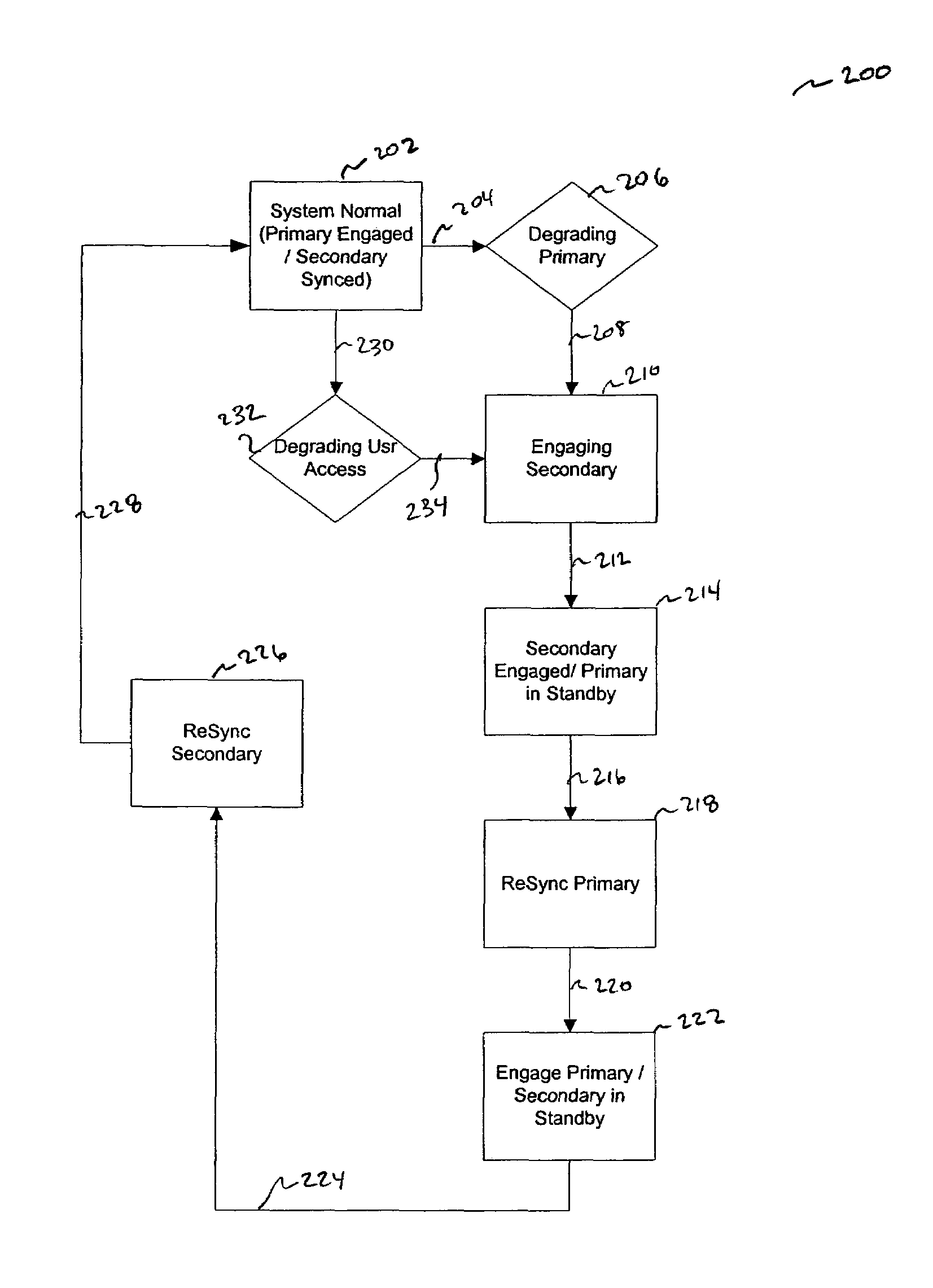
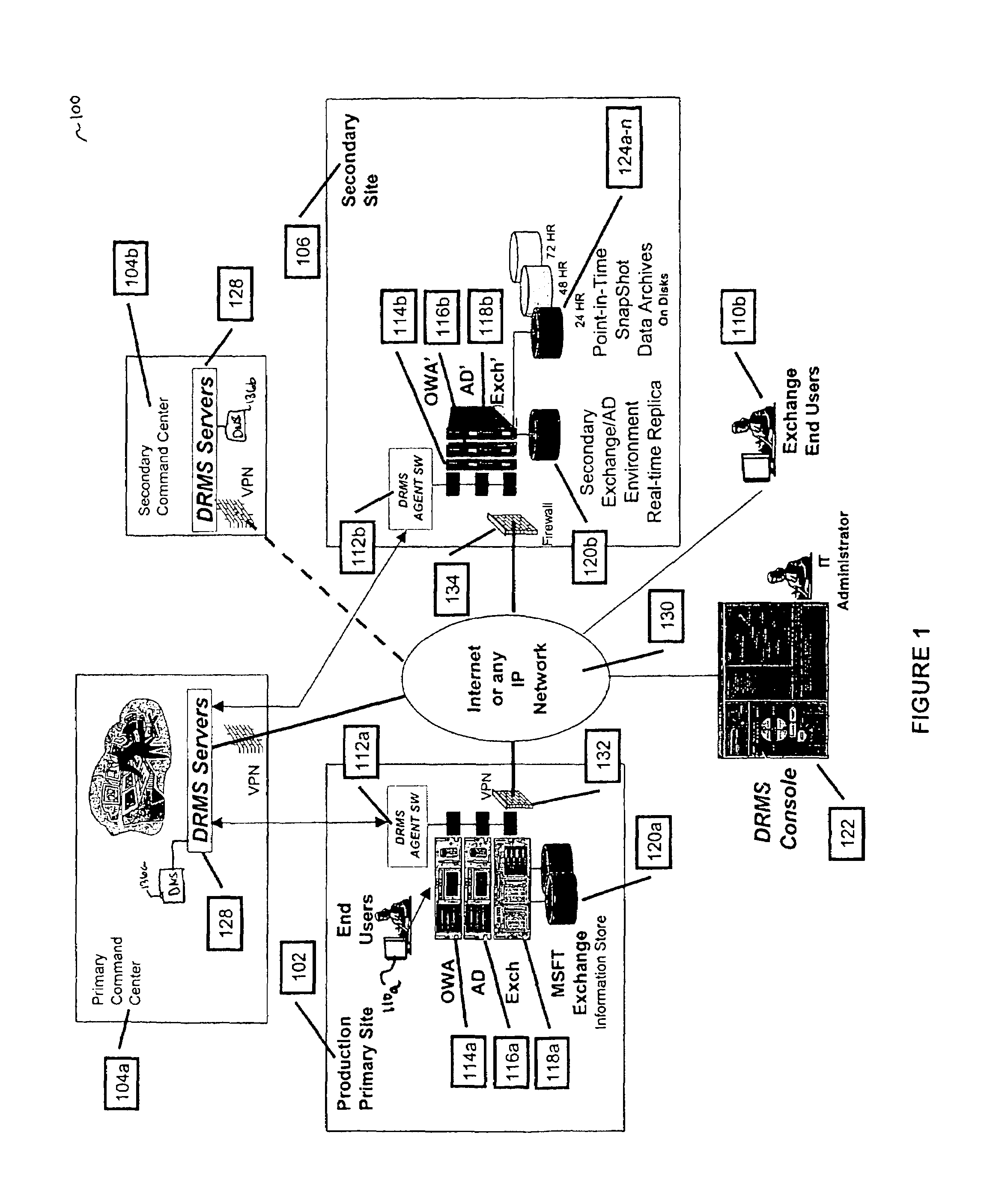
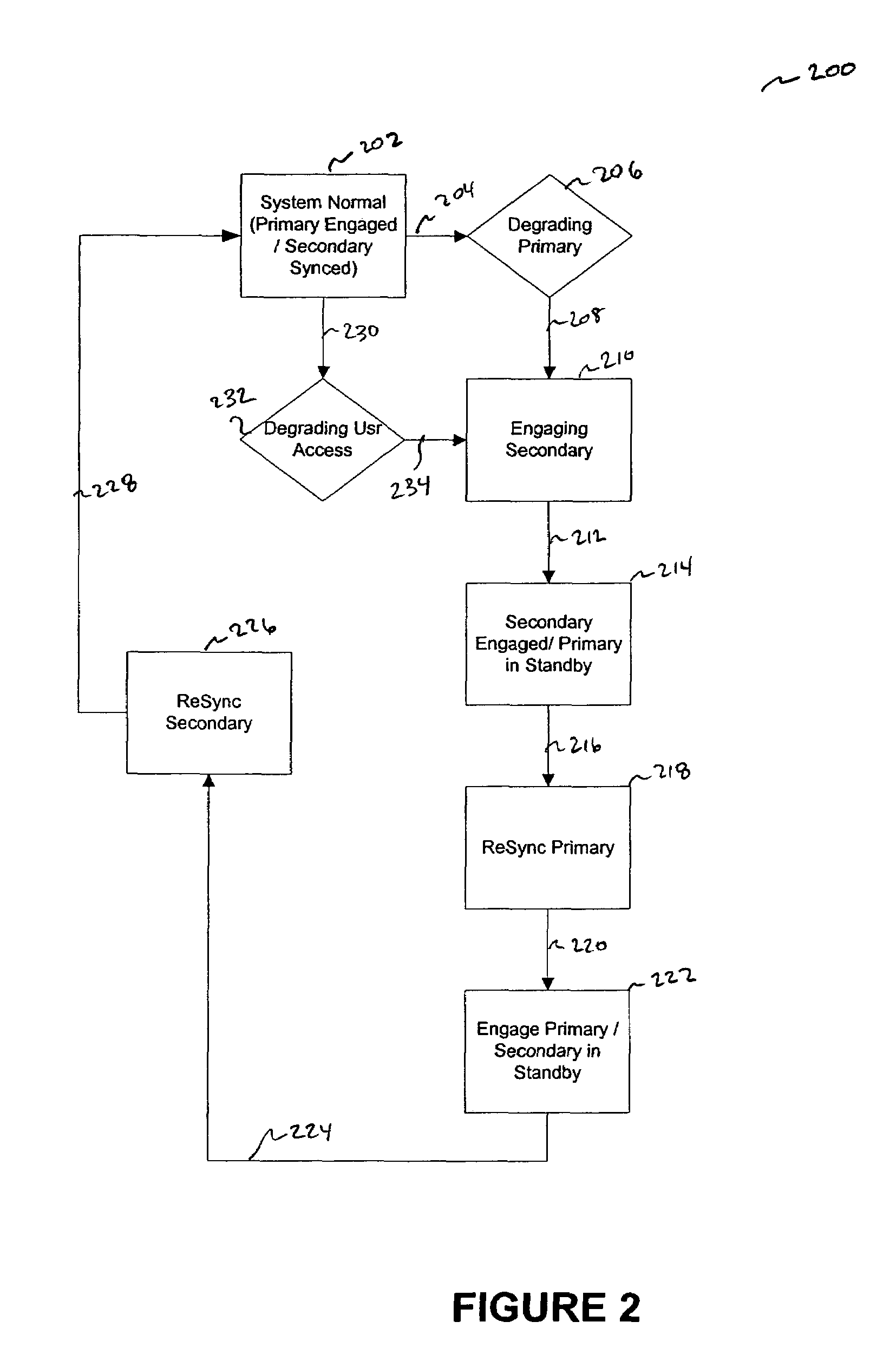
[0010]The present invention meets the above-identified needs by providing a system, method and computer program product for application monitoring, and application and end user switch-over control, in order to provide disaster recovery and fault tolerance (i.e., to respond to any system failures or a need to perform planned maintenance). That is, in an embodiment, the present invention provides automated recovery of an application executing within a computing environment (i.e., a primary server and network) by allowing for the transitioning to a secondary environment (e.g., a geographically dispersed secondary server and network) regardless of whether the primary server is down due to hardware failure, application failure, disaster or for scheduled maintenance.
[0011]In an embodiment, the present invention offers an enterprise the ability to assure that their computer system and its associated data will be highly available and will recover extremely rapidly, even in the event of a catastrophic facility outage. The present invention allows a service provider organization or an enterprise to provide an integrated service that eliminates complexity and reduces the cost to IT managers for assuring high availability and disaster recovery. The present invention includes a graphical user interface (e.g., a command console), application-specific monitoring of both a primary and secondary environments, and the ability to fully command and control the replication, failure switch-over and switch-back procedures between the two environments, and automatic end-user redirection between the two environments.
[0013]Another advantage of the present invention is that the disaster recovery process which conventionally can take, for example, 24 hours or longer, can be condensed into a 15-minute (or less) automated process.
[0015]Yet another advantage of the present invention is that it provides distributed systems command and control, data replication, and a customer-dedicated secondary computing infrastructure, to deliver comprehensive assurance of software application up-time and data integrity to an enterprise.
[0016]Yet another advantage of the present invention is that it wraps both high availability and disaster recovery for software applications into one package, and places control of the entire package in the hands of the enterprise's IT manager, network administrator or other authorized personnel.

Problems solved by technology

These “down-times” can be caused by facility disaster, hardware failures, software application failures, purposeful attacks from virus or simply scheduled (i.e., periodic) maintenance of one or more of the computer system's infrastructure components.
Therefore, any down-time of an enterprise's computer systems cuts into their personnel's productivity and thus the enterprise's overall productivity (and oftentimes, profitability).
Information Technology (IT) managers or network administrators charged with the responsibility to minimize down-time and maximize up-time of an enterprise's computer systems are thus faced with a challenge to “bomb-proof” such systems.
These resulting solutions are complex, difficult to maintain, and require significant investment.
For example, several software vendors offer remote data replication products for operating systems such as the Microsoft® Windows 2000™ operating system, but these software products do not help an enterprise's system environments stay healthy, and do not necessarily provide for application failure switch-over and switch-back procedures.

Method used


Image

  • System and method for application monitoring and automatic disaster recovery for high-availability
  • System and method for application monitoring and automatic disaster recovery for high-availability
  • System and method for application monitoring and automatic disaster recovery for high-availability

Examples


example implementations

X. Example Implementations

[0130]The present invention (DRM system 100, processes 200-700 or any part(s) or function(s) thereof) may be implemented using hardware, software or a combination thereof and maybe implemented in one or more computer systems or other processing systems. However, the manipulations performed by the present invention were often referred to in terms, such as adding or comparing, which are commonly associated with mental operations performed by a human operator. No such capability of a human operator is necessary, or desirable in most cases, in any of the operations described herein which form part of the present invention. Rather, the operations are machine operations. Useful machines for performing the operation of the present invention include general purpose digital computers or similar devices.

[0131]In fact, in one embodiment, the invention is directed toward one or more computer systems capable of carrying out the functionality described herein. An example...


PUM


Abstract

Stable and automated recovery of an application executing on a primary computer system by transitioning to a secondary computer system is provided. Intelligent agents installed on a primary client server allow the primary environment to be replicated on a host, secondary environment. This creates continuous availability of applications executing on the primary system via the mirrored host environment. Every transaction on the client environment (e.g., every piece of data) is replicated in real-time on the host environment. A simple mechanism (e.g., a button) is provided to allow access to the secondary environment thereby switching over from the client environment to the host environment in the case of, with respect to the primary environment, a disaster, a need to perform maintenance, system failure and the like.

Description

[0001]This application claims priority from U.S. Provisional Application No. 60 / 408,873, filed Sep. 9, 2002. The entirety of that provisional application is incorporated herein by reference.BACKGROUND OF THE INVENTION[0002]1. Field of the Invention[0003]The present invention generally relates to computer system environments, and more particularly to systems, methods and computer program products that provide disaster recovery and fault tolerance for such environments.[0004]2. Related Art[0005]In today's technological climate it is typical for an enterprise (i.e., a business concern, corporation, institution, organization, government agency or the like) to own and operate one or more computer systems (e.g., a collection of servers, desktops, laptops and the like all connected via local area networks (LANs), wide area networks (WANs) and the like). Such computer systems are used by enterprises so that their personnel (i.e., end users) can access not only software applications (e.g., s...

Claims


Application Information

Patent Timeline
Patent Type & Authority Patents(United States)
IPC IPC(8): G06F11/00G06F11/20H02H3/05H03K19/003H04L1/22H04L12/24H04L12/26
CPCG06F11/2023H04L43/0817H04L41/0654H04L41/22H04L41/046G06F11/2038
Inventor LICCIONE, JOHNJONES, KELLY M.
Owner MESSAGEONE LLC
Why Eureka
Try Eureka