Logical operation circuit and logical operation device

a logical operation and circuit technology, applied in the direction of heating types, pulse techniques, instruments, etc., can solve the problem that the circuit cannot perform a logical operation on data

Inactive Publication Date: 2008-09-23
ROHM CO LTD
View PDF6 Cites 42 Cited by
  • Summary
  • Abstract
  • Description
  • Claims
  • Application Information

AI Technical Summary

Problems solved by technology

However, such a conventional circuit cannot perform a logical operation on data even if it can store data.

Method used


Image

  • Logical operation circuit and logical operation device
  • Logical operation circuit and logical operation device
  • Logical operation circuit and logical operation device

Examples


Embodiment Construction

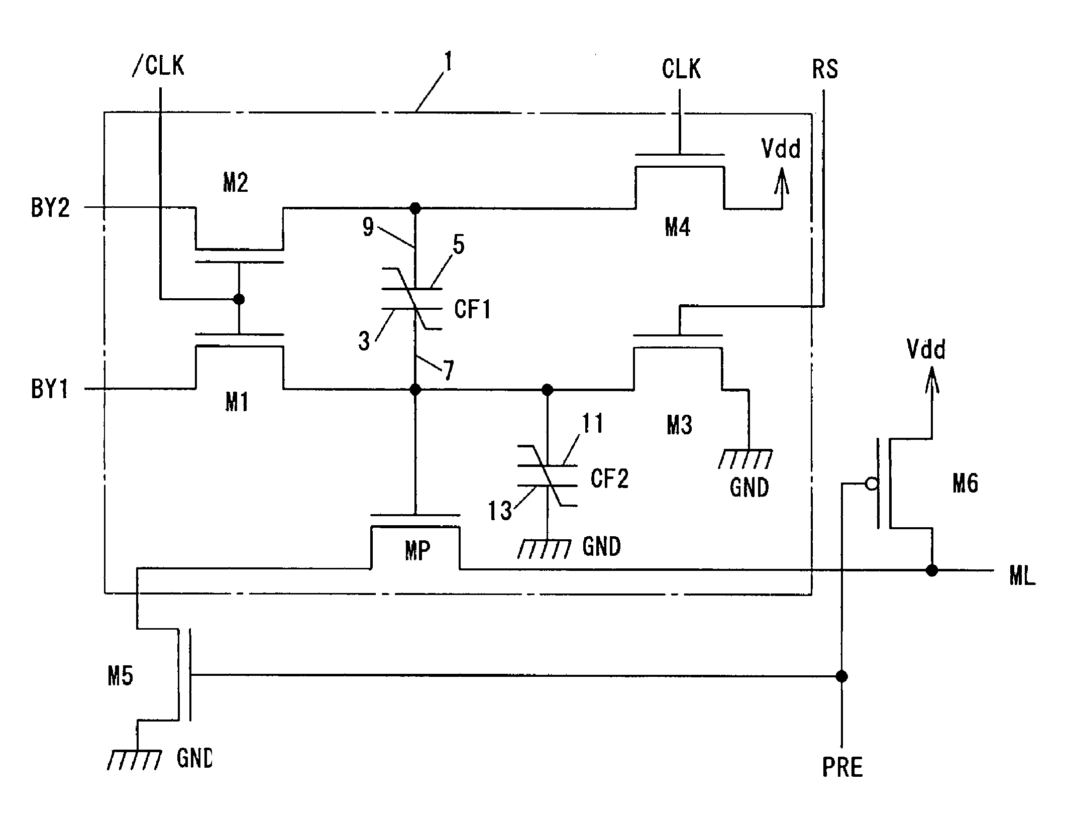
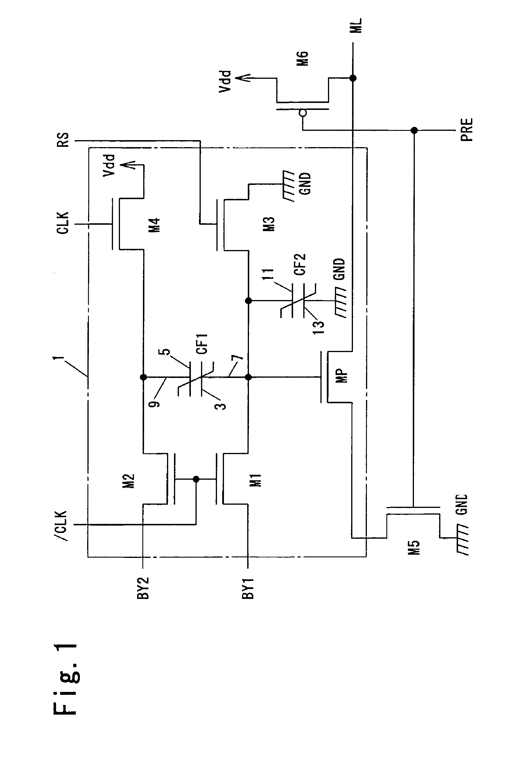
[0041]FIG. 1 is a circuit diagram illustrating a logical operation circuit 1 according to an embodiment of this invention. The logical operation circuit 1 has a first ferroelectric capacitor CF1 as a non-volatile memory element, a second ferroelectric capacitor CF2 as a load element, a transistor MP as an output transistor, and transistors M1, M2, M3 and M4. The second ferroelectric capacitor CF2 and the transistor MP constitute an operation result output section. The transistors MP, M1, M2, M3 and M4 are N-channel MOSFETs (metal oxide semiconductor field effect transistors).

[0042]The ferroelectric capacitor CF1 has a first terminal 3 connected to a first signal line 7 and a second terminal 5 connected to a second signal line 9. The first signal line 7 is connected to a gate terminal as a control terminal of the transistor MP.

[0043]The ferroelectric capacitor CF2 has a third terminal 11 connected to the first signal line 7 and a fourth terminal 13 connected to a ground potential GND...


PUM


Abstract

To provide a logical operation circuit and a logical operation device which can performs a logical operation using a ferroelectric capacitor. The area ratio between the ferroelectric capacitors CF1 and CF2 are set such that the potential difference Vdef between voltages Va1 and Va0 is as large as possible, and a transistor MP has a threshold voltage Vth which is about ½·(Va0+Va1). Thus, the ON / OFF operation margin of the transistor MP can be significantly large. As a result, a reading process can be performed at a high speed without using an amplifying circuit such as a sense amplifier. Also, the logical operation circuit and the logical operation device can be highly integrated with ease since no sense amplifier is used.

Description

CROSS-REFERENCE TO RELATED APPLICATION[0001]The entire disclosure of Japanese Patent Application No. 2003-280520 filed on Jul. 25, 2003 including their specification, claims, drawings and summary are incorporated herein by reference in its entirety.BACKGROUND OF THE INVENTION[0002]1. Field of the Invention[0003]This invention relates to a logical operation circuit and a logical operation device and, more particularly, to a logical operation circuit and a logical operation device using a ferroelectric capacitor.[0004]2. Description of a Prior Art[0005]A non-volatile memory is known as a circuit using a ferroelectric capacitor (see JP-A-2000-299000, for example). It is possible to realize a rewritable non-volatile memory which can operate on a low voltage by using a ferroelectric capacitor.[0006]However, such a conventional circuit cannot perform a logical operation on data even if it can store data.SUMMARY OF THE INVENTION[0007]An object of this invention is to solve the problem of s...

Claims


Application Information

Patent Timeline
Patent Type & Authority Patents(United States)
IPC IPC(8): G06F7/38H03K19/185
CPCH03K19/185
Inventor FUJIMORI, YOSHIKAZU
Owner ROHM CO LTD
Why Eureka
Try Eureka