
Air-independent fuel combustion energy conversion

a technology of fuel combustion and independent combustion, which is applied in the direction of steam engine plants, steam engine plants, machines/engines, etc., can solve the problems of agglomeration and clogging problems, expulsion of a detectable signature from the seawater vessel being propelled, and excessive supply of oxygen extracted

Active Publication Date: 2008-10-07
MCDONNELL THOMAS
View PDF7 Cites 13 Cited by
  • Summary
  • Abstract
  • Description
  • Claims
  • Application Information

AI Technical Summary

Benefits of technology

[0005]Pursuant to the present invention, both aluminum (Al) and magnesium (Mg) are utilized to form with silicon (Si) an alloy such as Mg2Al4Si5 or a similar compound of a fuel mixture fed into a combustor with an oxidant. The combustor is enclosed within a steam chamber into which a working fluid such as water is injected. Combustion of the fuel mix

Problems solved by technology

Additionally an internal combustion engine and turbine associated with the combustor generally require an excessive supply of oxygen extracted from the oxidant for operational support.
Furthermore, the combustion product discharged from the combustor, such as carbon dioxide (CO2), may result in expulsion of a detectable signature from the seawater vessel being propelled.
However, its associated combustion discharge by-product may form a slag responsible for agglomerating and clogging problems with respect to the exhaust port of the combustor.

Method used


Image

  • Air-independent fuel combustion energy conversion
  • Air-independent fuel combustion energy conversion
  • Air-independent fuel combustion energy conversion

Examples


Embodiment Construction

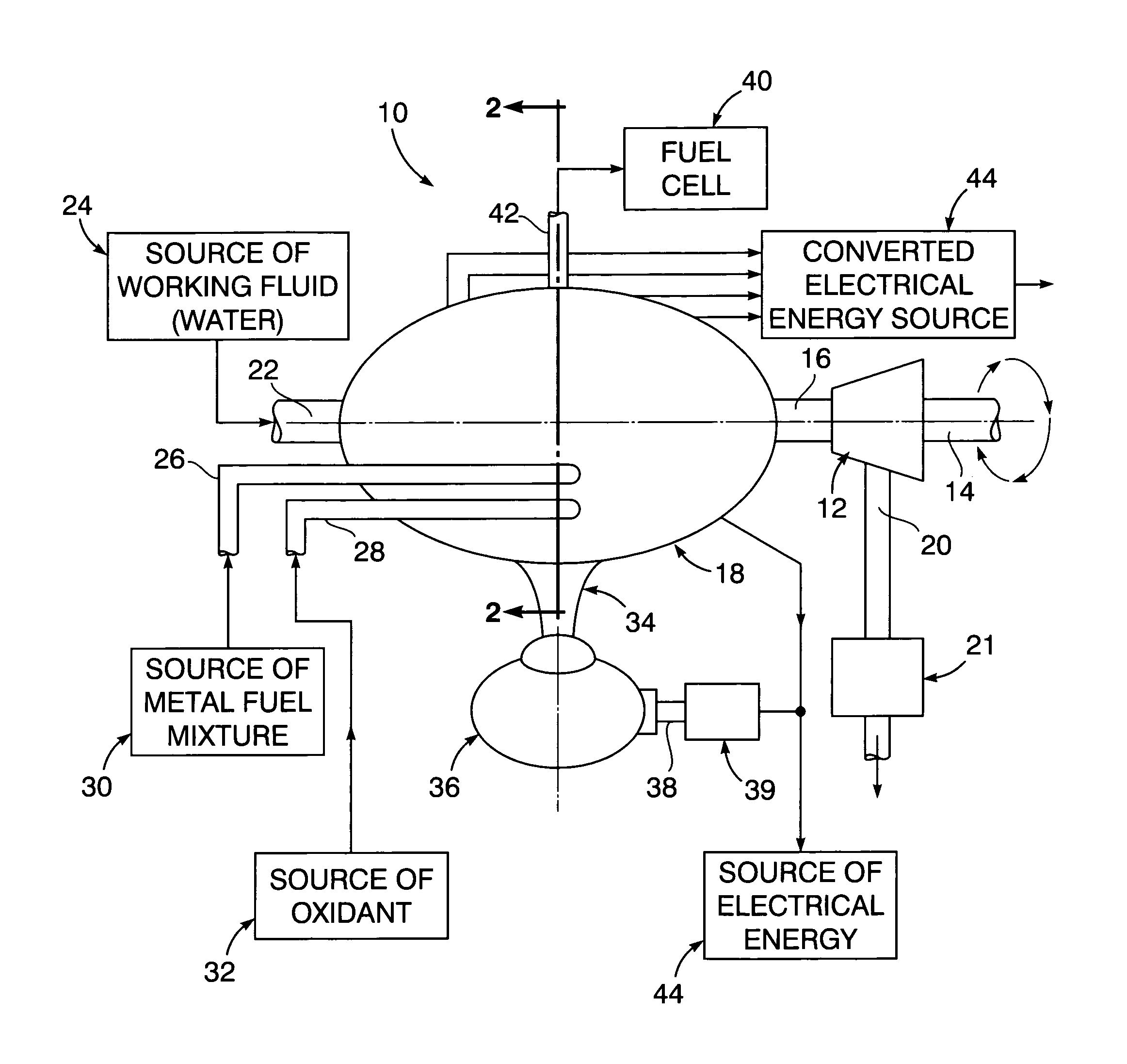
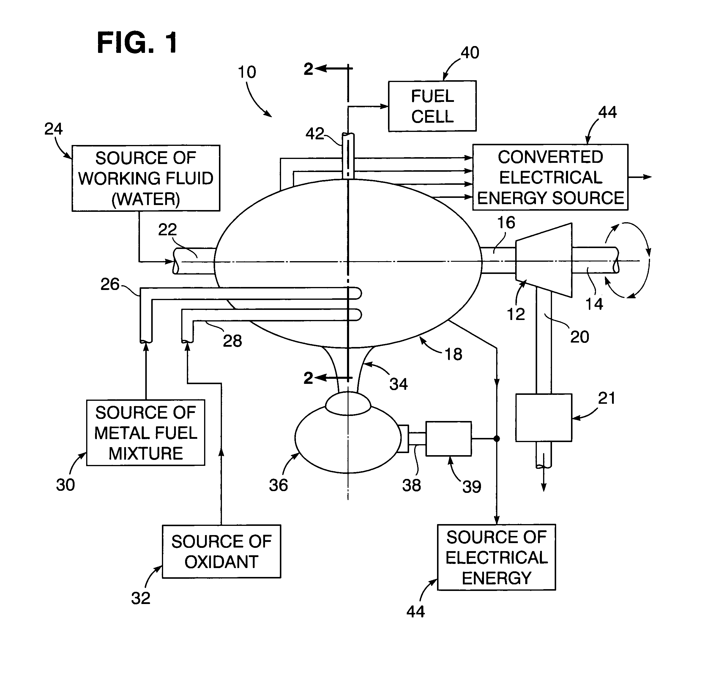
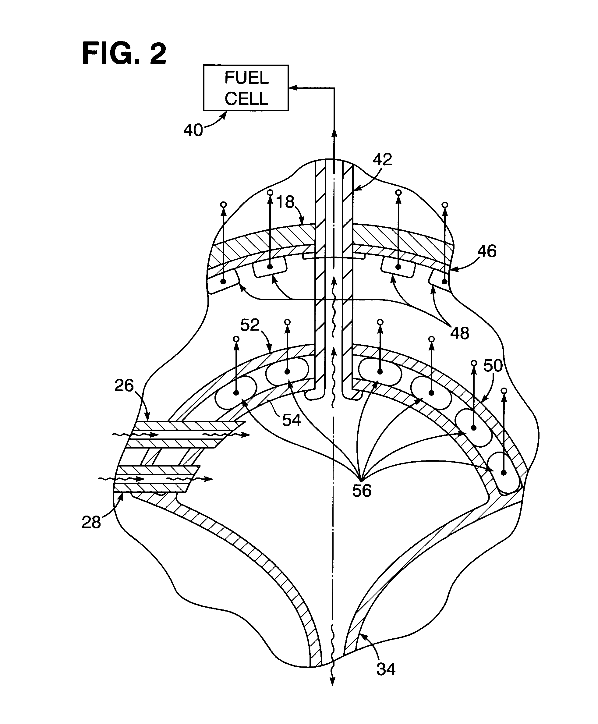
[0011]Referring now to the drawing in detail, FIG. 1 illustrates an air-independent type of fuel combustion energy conversion system 10 through which sea vessel vehicles may be propelled within a seawater environment. Accordingly, the system 10 has a power turbine 12 associated therewith from which a propulsion drive shaft 14 extends to mechanically impart rotational energy to propellers of a propulsion unit, associated with the sea vessel for example. The rotational energy output of the turbine 12 to the shaft 14 is derived from pressurized steam delivered through a steam line 16 from a steam chamber enclosure 18. Low pressure steam is then discharged from the turbine 12 through an exhaust line 20 into a condenser 21 as a result of combustion within the chamber enclosure 18. The pressurized steam supplied to the turbine 12 from the chamber enclosure 18 is derived from a working fluid, such as water, fed into the chamber enclosure 18 through a working fluid infeed line 22 from a sou...


PUM


Abstract

A metallic fuel mixture including solidic powders such as silicon, aluminum and magnesium together with an oxidant, and steam and hydrogen are fed into a combustor to undergo combustion therein. The combustor is positioned within a steam chamber enclosure filled with water as working fluid which is heated by the combustion. The heated water within the stream chamber enclosure is thereby converted into pressurized steam fed into a turbine for operation thereof to impart rotation to a shaft thereby propelling a sea vessel within which the steam chamber enclosure is housed. During such combustion, discharge from the combustor of a liquid by-product occurs as outflow through an exhaust funnel into a collector from which the by-product is processed for ejection into seawater without signature detection. The radiant energy generated by such combustion may be converted by photovoltaic cells within the steam chamber enclosure into electrical energy made available outside of the steam chamber enclosure, while some of the heat energy generated by the combustion within the combustor may also be converted by thermoelectric cells into electrical energy made available outside of the steam chamber enclosure.

Description

[0001]The present invention relates generally to combustion of fuel for generating propulsion energy within a seawater environment.STATEMENT OF GOVERNMENT INTEREST[0002]The invention described herein may be manufactured and used by or for the Government of the United States of America for governmental purposes without the payment of any royalties thereon or therefore.BACKGROUND OF THE INVENTION[0003]Air-independent fuel combustion systems for generating energy to propel a sea vessel within a seawater environment requires use of an oxidant within a combustor. Additionally an internal combustion engine and turbine associated with the combustor generally require an excessive supply of oxygen extracted from the oxidant for operational support. Furthermore, the combustion product discharged from the combustor, such as carbon dioxide (CO2), may result in expulsion of a detectable signature from the seawater vessel being propelled.[0004]Aluminum and magnesium powders form solidic powder mi...

Claims


Application Information

Patent Timeline
IPC IPC(8): F01K13/00
CPCF01K27/02F22B1/18
Inventor LYNCH, WILLIAM A.SONDERGAARD, NEAL A.
Owner MCDONNELL THOMAS
Learn More