Radiator for light emitting unit, and backlight device

a technology of light emitting units and backlight devices, which is applied in the direction of lighting and heating equipment, instruments, transportation and packaging, etc., can solve the problems of vibration or unintentional movement, large amount of heat generated by leds, and degradation of display accuracy, so as to enhance the efficiency of cooling function, high luminance, and stable operation

Inactive Publication Date: 2008-10-07
SONY CORP
View PDF5 Cites 37 Cited by
  • Summary
  • Abstract
  • Description
  • Claims
  • Application Information

AI Technical Summary

Benefits of technology

[0010]In the LED backlight device, when the heat sink is attached directly to the wiring substrate on which, for example, a multiplicity of LEDs are mounted or to a back plate supporting the wiring substrate, an effective heat radiation can be achieved. In the LED backlight device, however, circuit packages for driving the LEDs or for controlling the lighting and the like are mounted to the back plate. For stable operation of these packages, in the LED backlight device, it may be necessary to provide appropriate bracket members or the like for constituting heat-insulating members, for example, by being interposed between the LED backlight device and the back plate and for contriving isolation from the heat sink. The presence of the bracket members or the like increases the thickness of the LED backlight device and lowers the efficiency of assembling operation or the like.
[0011]Thus, there is a need for provision of a radiator of a thin type structure capable of efficiently radiating the heat generated from a multiplicity of light emitting diodes. Also, there is a need for provision of a backlight device in which a multiplicity of light emitting diodes are provided for contriving an. enhancement of luminance of a display panel, the heat generated from the light emitting diode group is efficiently radiated to make uniform the temperature distribution over the whole area of the display panel, and a thinner form can be contrived.
[0013]The radiator is provided for the light emitting unit which has a multiplicity of light emitting diodes as a light source and which thereby emit light at a high luminance. In the radiator, a large amount of heat is generated by the lighting operations of the light emitting diodes, and the heat thus generated is conducted to the radiating plate formed of a metallic member having good thermal conductivity such as, for example, an aluminum material. In the radiator, besides, the heat pipe having a high heat conduction performance is mounted in the heat pipe fitting recessed portion formed in the radiating plate, whereby the heat is radiated through efficient conduction to a radiating section via the radiating plate and the heat pipe. In the radiator, further, the heat pipe is kept in close contact with the inner wall of the heat pipe fitting recessed portion, so that the conduction of heat from the radiating plate to the heat pipe is performed efficiently, and the heat generated from the light emitting diodes is radiated at the radiating section.
[0015]In the backlight device, a light emitting diode group having a multiplicity of light emitting diodes provided in the backlight unit is used as a light source, and the light emitting diodes are put into lighting operation to supply a high capacity of display light to the transmission type display panel so that an image and the like can be displayed at high luminance. In the backlight device, a large amount of heat generated as a result of lighting operations of the light emitting diodes and accumulated in a space portion between the backlight unit and the transmission type display panel is efficiently radiated by the radiating unit, whereby the transmission type display panel is illuminated in a stable condition. In the backlight device, the heat generated from the light emitting diodes is efficiently radiated by the radiating unit and the transmission type display panel is brought to a predetermined temperature which prevails substantially uniformly over the whole surface of the display panel, whereby generation of irregularity in color and the like is prevented, and images and the like can be stably displayed at high luminance.
[0017]According to the radiator for a light emitting unit according to one embodiment of the present invention configured as above, the large quantity of heat generated as a result of the light operations of a multiplicity of light emitting diodes is efficiently conducted by the radiating plate and the heat pipe to the radiating section provided at a separate location. Therefore, according to the radiator for a light emitting unit, a light emitting unit which has a multiplicity of light emitting diodes as a light source and which emit light at high luminance through a stable operation can be obtained, without providing a radiating section directly at the light emitting portion. In addition, according to the radiator for a light emitting unit, the heat pipe is mounted in the heat pipe fitting recessed portion formed in the radiating plate in the state of making close contact with the heat pipe fitting recessed portion, so that it is possible to contrive an enhancement of the efficiency of the cooling function and to contrive a reduction in the thickness of the light emitting unit.
[0018]Besides, in the backlight device according to another embodiment of the present invention, a high capacity of display light is supplied to the transmission type display panel by the backlight unit having a light emitting diode group composed of a multiplicity of light emitting diodes as a light source, whereby an optical display at high luminance can be achieved. In the backlight device, a highest-efficiency portion of the radiating plate absorbing the large quantity of heat which is generated upon lighting operations of the light emitting diodes and which is accumulated in the space portion between the backlight unit and the transmission type display panel is cooled by the heat pipe having a high-efficiency cooling ability, whereby efficient heat radiation is achieved, and the transmission type display panel is permitted to perform optical display in a stable condition. In the backlight device, the heat pipe is fitted in the heat pipe fitting recessed portion formed in the radiating plate, whereby it is possible to reduce the thickness of the radiating unit having the high radiation performance and to thereby contrive a reduction in the overall thickness of the backlight device. In the backlight device, the transmission type display panel is kept at a substantially uniform temperature over the whole area thereof, whereby generation of irregularity in color and the like is prevented, and a stable display can be achieved.

Problems solved by technology

Meanwhile, in the LED backlight device, a multiplicity of LEDs is provided and a large quantity of heat is generated from the LEDs.
In addition, the LED backlight device includes the diffusion plate and the reflective film as above-mentioned, and generation of deformation, denaturing or the like in these optical films due to the elevated temperature leads to degradation of the display accuracy.
However, the configuration in which the cooling airflow is blown directly to the diffusion film and the reflective film cannot be adopted, since this approach leads to the generation of vibrations or unintentional movements.
In the LED backlight device, there are the restrictive conditions that the thermally conductive member should not be disposed directly in the closed space portion because the member would shield the display light, that it is desirable to radiate the head from the closed space portion efficiently and uniformly, that the closed space portion should be connected to the heat sink through the shortest course so as to achieve efficient heat radiation, and the like, and the structure is complicated for fulfilling these conditions.
Besides, in the LED backlight device, such phenomena as irregularity in color would be generated in the case where the heat radiation is not performed appropriately and where the liquid crystal panel does not have a uniform temperature distribution over the whole area thereof.
The presence of the bracket members or the like increases the thickness of the LED backlight device and lowers the efficiency of assembling operation or the like.

Method used


Image

  • Radiator for light emitting unit, and backlight device
  • Radiator for light emitting unit, and backlight device
  • Radiator for light emitting unit, and backlight device

Examples


Embodiment Construction

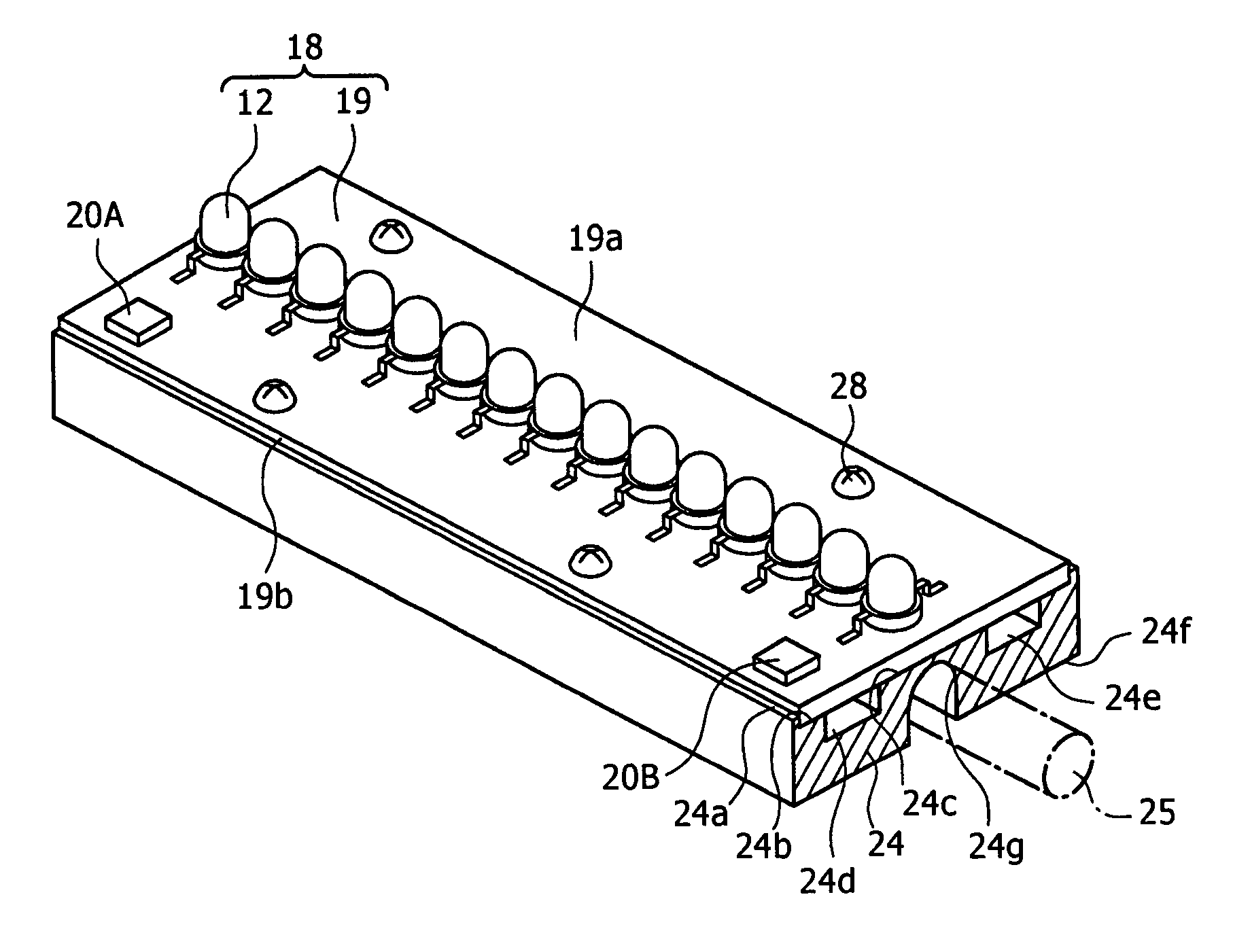
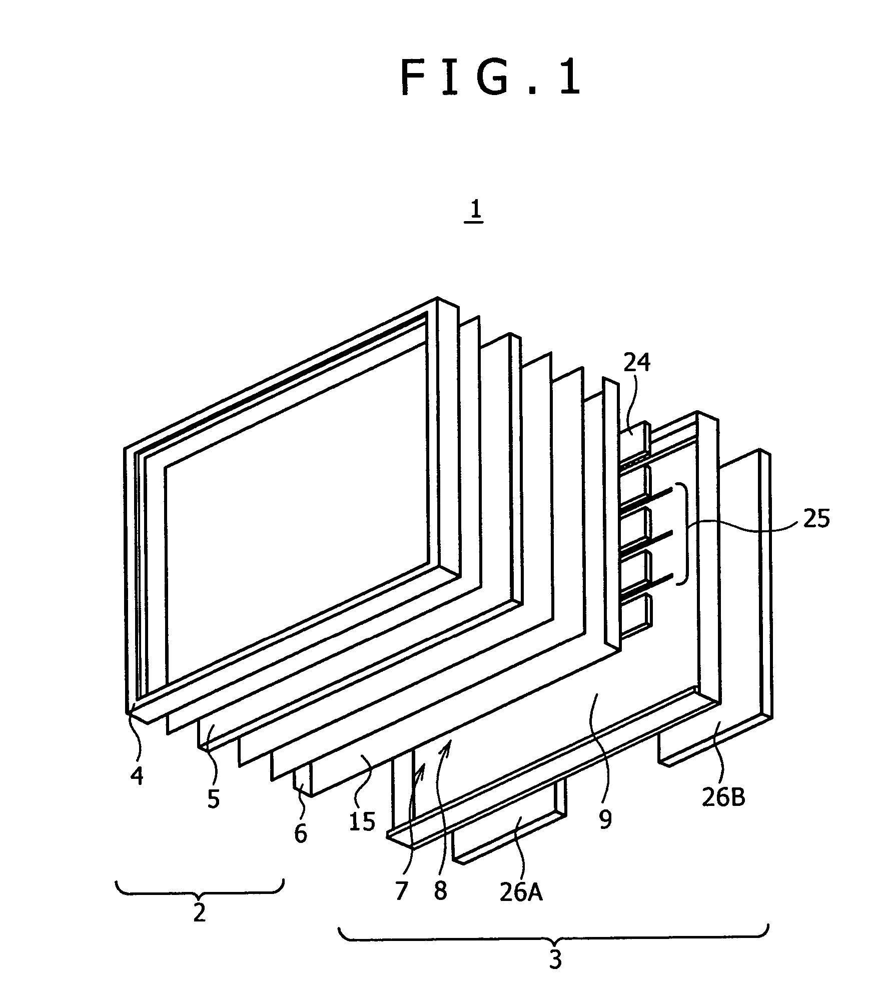
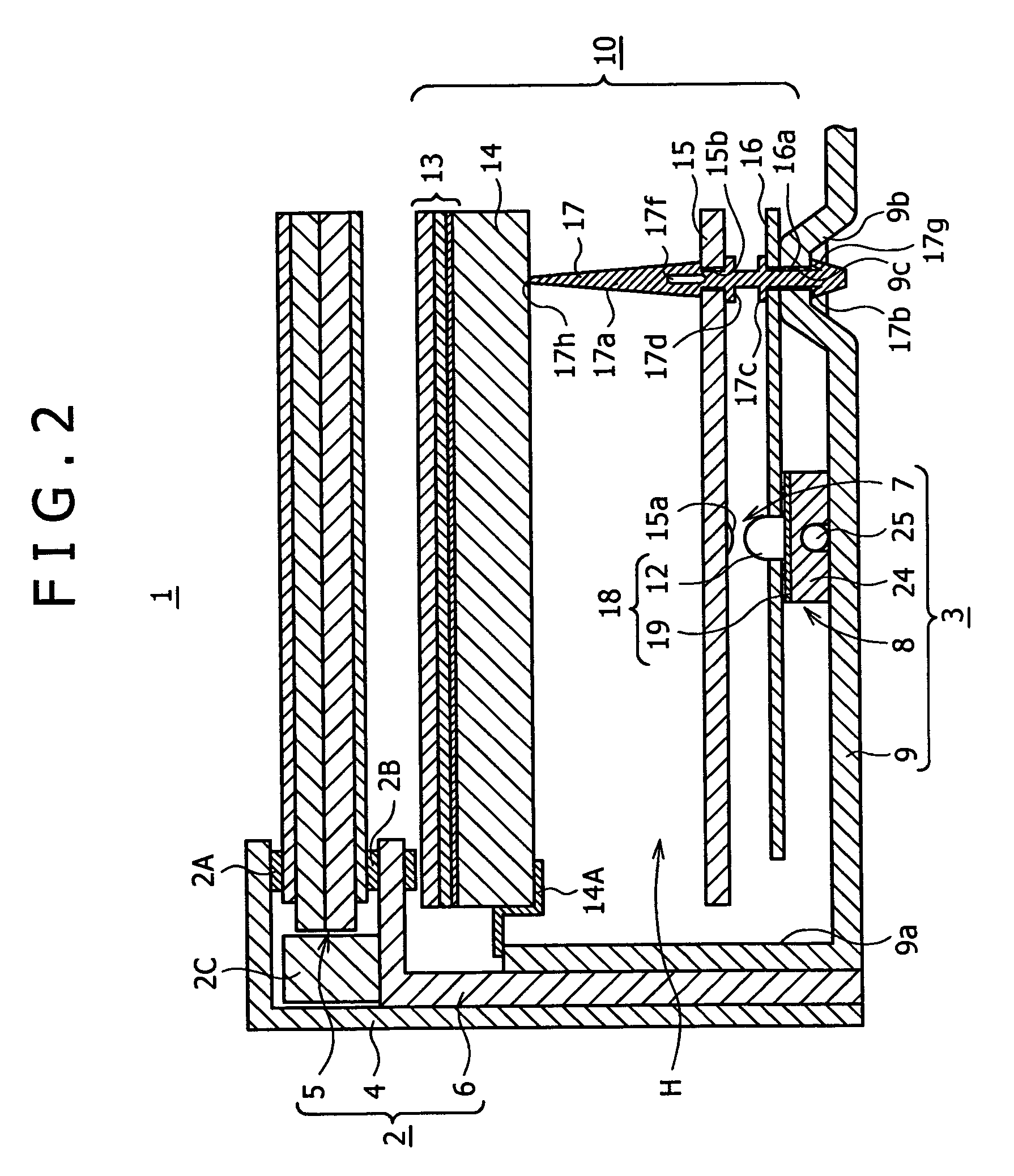
[0033]Now, a transmission type liquid crystal display panel 1 shown in the figures as an embodiment of the present invention will be described in detail below. The transmission type liquid crystal display panel 1 is used as a display panel of a TV set having a large display screen of 40 inches or more, for example. As shown in FIGS. 1 and 2, the transmission type liquid crystal display panel 1 includes a liquid crystal panel unit 2, and a backlight unit 3 combined with the back side of the liquid crystal panel unit 2 for supplying display light to the latter. The liquid crystal panel unit 2 includes a frame-like front frame member 4, a liquid crystal panel 5, and a frame-like back frame member 6 for clamping an outer peripheral portion of the liquid crystal panel 5 between itself and the front frame member 4 through spacers 2A, 2B, a guide member 2C and the like.

[0034]Though details are omitted, the liquid crystal panel 5 has a structure in which a liquid crystal is sealed between a...


PUM


Abstract

The present invention provides a radiator for a light emitting unit, annexed to the light emitting unit including a multiplicity of light emitting diodes mounted on substantially the same axis line on a first principal surface of a wiring substrate. The radiator includes a radiating plate and a heat pipe. The radiating plate is combined with the wiring substrate, with a first principal surface faced as a faying surface to a second principal surface opposite to the first principal surface of the wiring substrate, and is provided with a heat pipe fitting portion. The heat pipe is mounted into the heat pipe fitting portion of the radiating plate while keeping close contact with the inner wall of the heat pipe fitting portion. The heat generated from the light emitting diode group is transferred to a radiating means through the radiating plate and the heat pipe.

Description

CROSS REFERENCES TO RELATED APPLICATIONS[0001]The present invention contains subject matter related to Japanese Patent Application JP 2004-136919 filed in the Japanese Patent Office on Apr. 30, 2004, the entire contents of which being incorporated herein by reference.BACKGROUND OF THE INVENTION[0002]The present invention relates to a backlight device provided, for example, in a transmission type liquid crystal display (LCD) or the like, and to a radiator annexed to the backlight device.[0003]The liquid crystal display is suitable for contriving a larger display screen, a lighter weight, a thinner shape, a lower power consumption and the like, as compared with the cathode ray tube (CRT). Therefore, liquid crystal displays have come to be used for TV sets and various displays, together with, for example, the self-light-emitting type PDPs (Plasma Display Panels) and the like. The liquid crystal display has a liquid crystal panel in which liquid crystals are sealed between two transpare...

Claims


Application Information

Patent Timeline
Patent Type & Authority Patents(United States)
IPC IPC(8): F21V7/20F21V29/00G01D11/28F21V29/505
CPCG02F1/133603G02F2001/133628G02F1/133628H05K7/2099
Inventor HAFUKA, TABITOSHIBATA, HIROKAZU
Owner SONY CORP
Why Eureka
Try Eureka