[0012]The present invention provides a simple technique for calibrating a camera using phase
estimation, and a continuous gray scale (or
color scale) rather than sharp-edged target recognizable by the camera, for example a multi-sinusoidal calibration target pattern. Preferably the calibration target includes a pattern such that the camera-captured image of the pattern enables
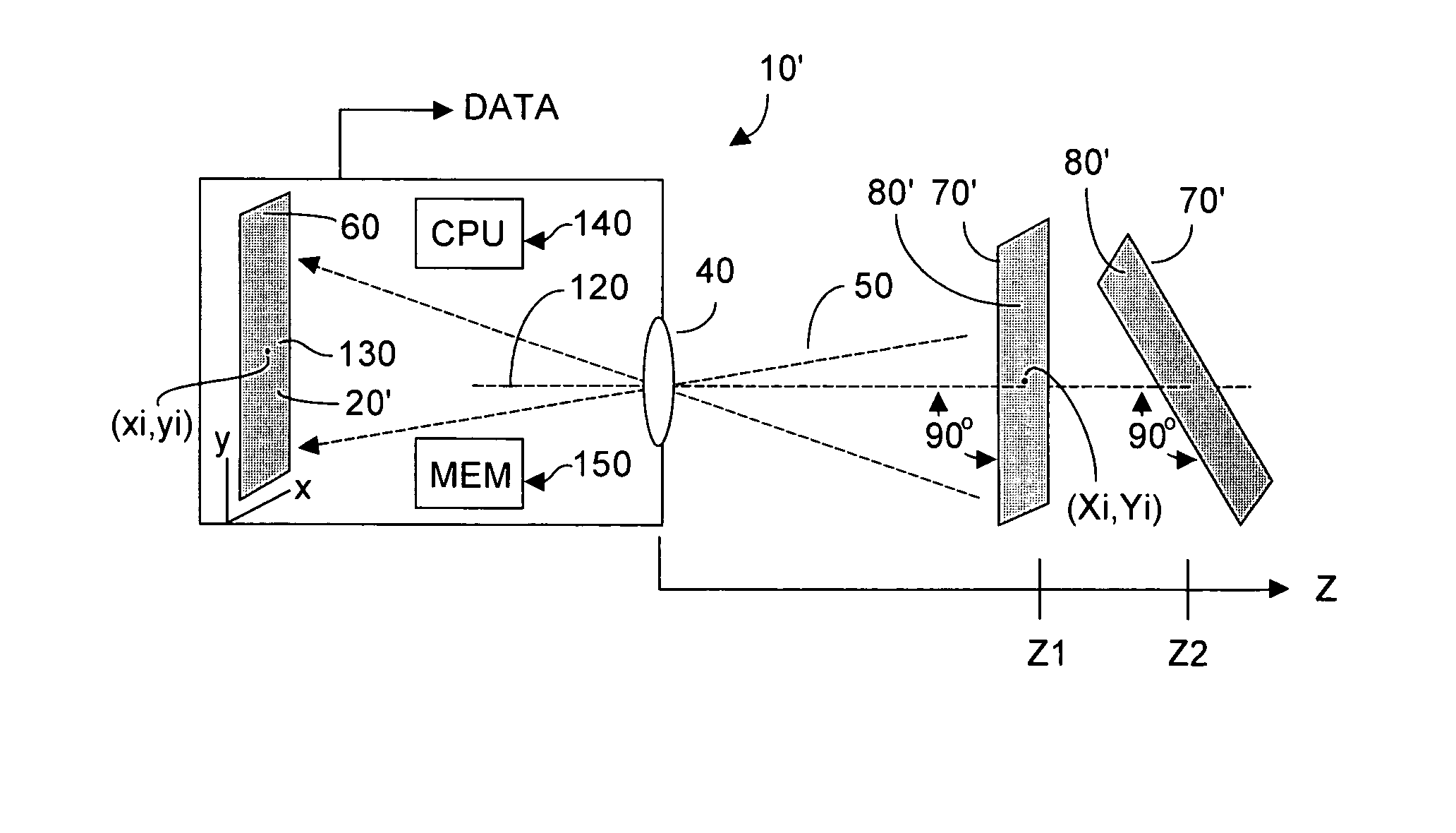
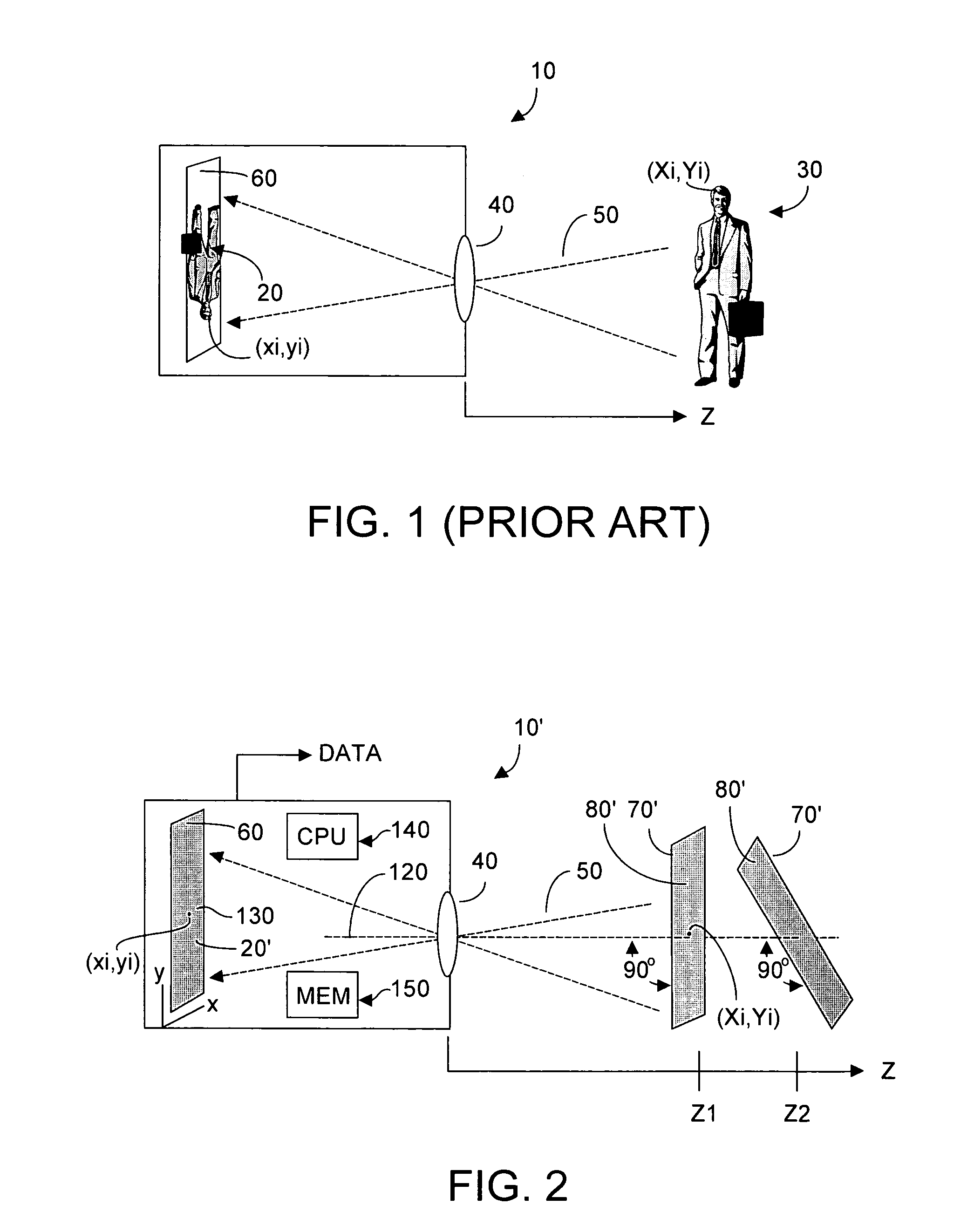
spatial calibration of the camera enabling the camera to discern real-world (Xi,Yi) calibration target coordinates and to enable a mapping between such coordinates and pixel locations (xi,yi) on the camera-captured image. The calibration target is disposed a known distance Z from the camera under calibration, with the target plane normal to the
optical axis of the camera. Although the target preferably is formed on a plane, the
target surface could in fact be curved, where the curvature is known as a function of Z. The camera is used to capture an image of the calibration target pattern, which captured image is then analyzed to build a unique 1:1 mapping relationship between each pixel (xi,yi) in the captured image, and the real-world (Xi,Yi) location of points in the calibration target pattern. (Uniqueness ignores 2π
aliasing that can result from the preferably repetitive nature of the calibration pattern.) The mapping relationship can be stored, for example in a look-up-table, and used with knowledge of Z to calculated (xi,yi,zi) address for any point (Xi,Yi,Zi) in real-
world space that is subsequently imaged by the camera at a known distance Z.
[0013]To improve quality of the calibration process, preferably the calibration target image is correctively pre-distorted such that the camera-captured image will be substantially undistorted. Within the plane of the calibration target, the pattern is substantially free of two-dimensional
ambiguity (but for singularity points defined in the pattern). Application of such a calibration target pattern results in the presence of a
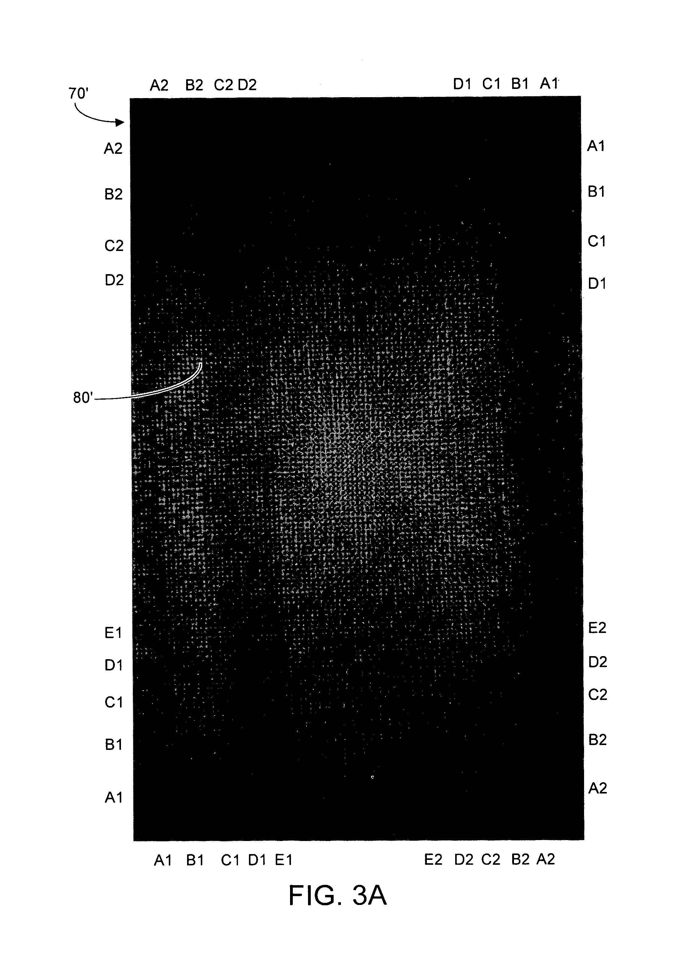
distortion field at each point (xi,yi) in the captured image. Preferably the calibration target pattern is defined using first and second frequencies that produce a calibration pattern exhibiting wavefronts with a
wavelength greater than two and less than about twenty pixels of the captured image. Location of these wavefronts in the calibration target pattern is precisely known. Alternatively, first and second targets could be used, each defined using a single (but different) frequency to exhibit a single pattern of such wavefronts, although calibration using multiple targets would generally take longer than calibration with a single, multi-frequency
wavefront-producing target.
[0018]Applicant has discovered that a target pattern F(X) having as few as two frequency components will suffice to uniquely determine the (xi,yi) components of the correspondence field at each image point created by the camera from the calibration pattern target. Preferably the frequency components exhibit high spatial content, to promote calibration accuracy. However as noted, calibration can also occur using a single frequency to create a calibration target.
[0019]The image of the target calibration pattern captured by the camera under calibration will contain phase patterns such that the pattern changes in any direction. The preferably pre-distorted target calibration pattern captured by the camera system will be substantially undistorted, and as a result, a substantially linear grid of wavefronts is present in this camera-captured image. Further, density or
granularity of the wavefronts in the captured image is substantially constant throughout the plane of the captured image. As a result, quality of the captured image is substantially constant throughout the image. Further, resolution of the grid-like wavefronts can approximate, without exceeding, the
spatial image capability of the camera system
optics.
[0021]As such, calibration according to the present invention exhibits substantial insensitivity to orientation and scale of the calibration pattern target and enables unique and reasonably rapid calibration of every pixel to a corresponding point in the calibration image target. Further, the present calibration technique is relatively robust as to variations in brightness and contrast, and provides a dense correspondence, even in the presence of substantial
distortion in the camera optical system. In essence, use of the camera system response to the calibration target permits
inference of what camera pixels correspond to what points on the calibration target, from which
data vector angles between pixel points to the calibration target points may be inferred. As such, camera system distortions, for example and without limitation optical system distortions, can be identified and compensated for via calibration.

