[0008]When the thermally insulating regions are arranged around the interior space, the interior space is protected particularly effectively from the emission of
thermal energy through the wall of the electrical insulator. In particular when the interior space is heated, excess
thermal emission can therefore be prevented. In this case, provision may be made for the interior space to be surrounded along its entire extent by the thermally insulating region or else for only sections to be surrounded by a thermally insulating region. It is thus possible to provide sections on the electrical insulator which have particularly effective
thermal insulation, as required. Zones are therefore produced in a targeted manner which allow for rapid cooling and therefore have a
temperature difference in comparison with the more insulated regions. It is therefore possible to encourage the production of
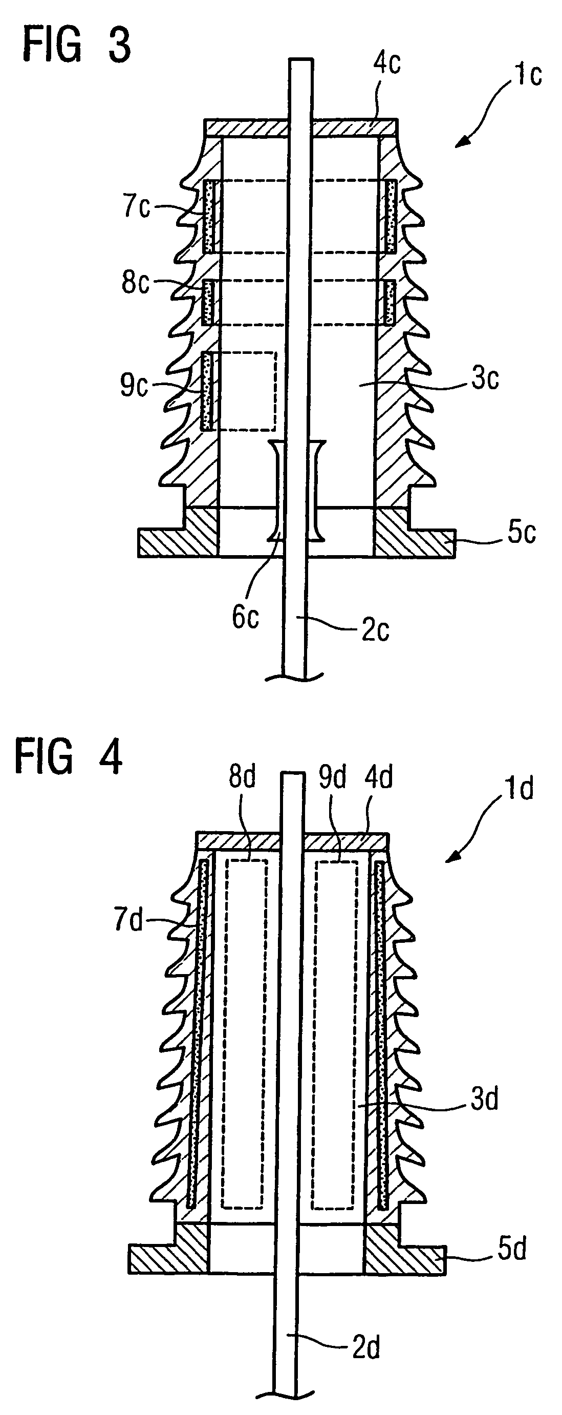
convection in the interior space of the electrical insulator. The interior space of the insulator can be filled with various built-in components. Such built-in components are, for example, drive elements, cables and lines, etc. The insulator may also be in the form of a so-called post insulator, for example, and have assemblies in insulated fashion.
[0011]It may be particularly advantageous if the insulator and the thermally insulating region are arranged coaxially with respect to the
electrical conductor.
[0012]The coaxial arrangement provides advantages as regards the
dielectric design of the insulator. In particular, designing the thermally insulating region as a coaxially surrounding layer makes it possible to adhere to the known design for insulators for bushings. Owing to the thermally insulating region, only the thickness of the wall of the insulator which extends around the interior space is changed. It is furthermore possible to adhere to the basic design for known bushings.
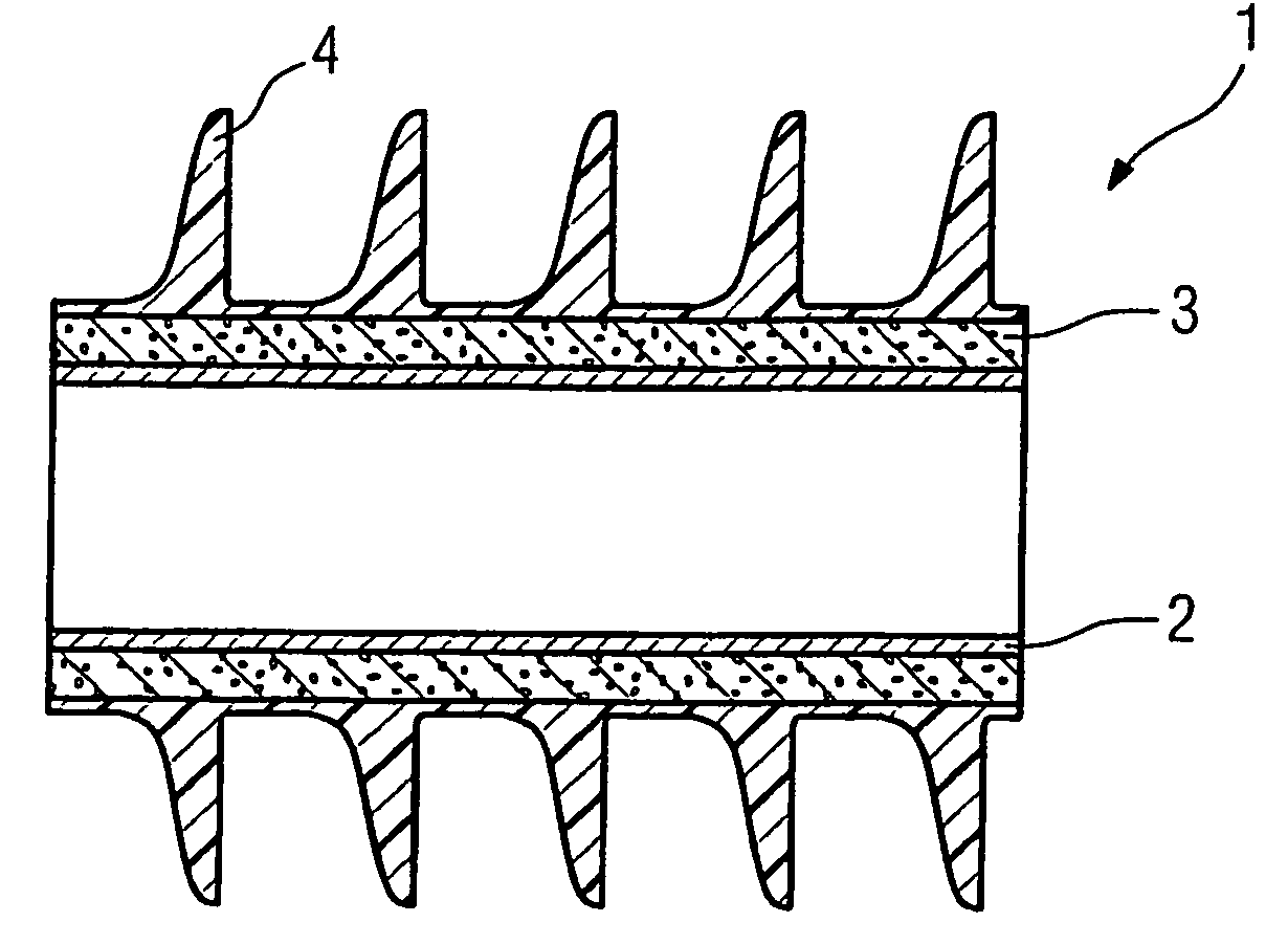
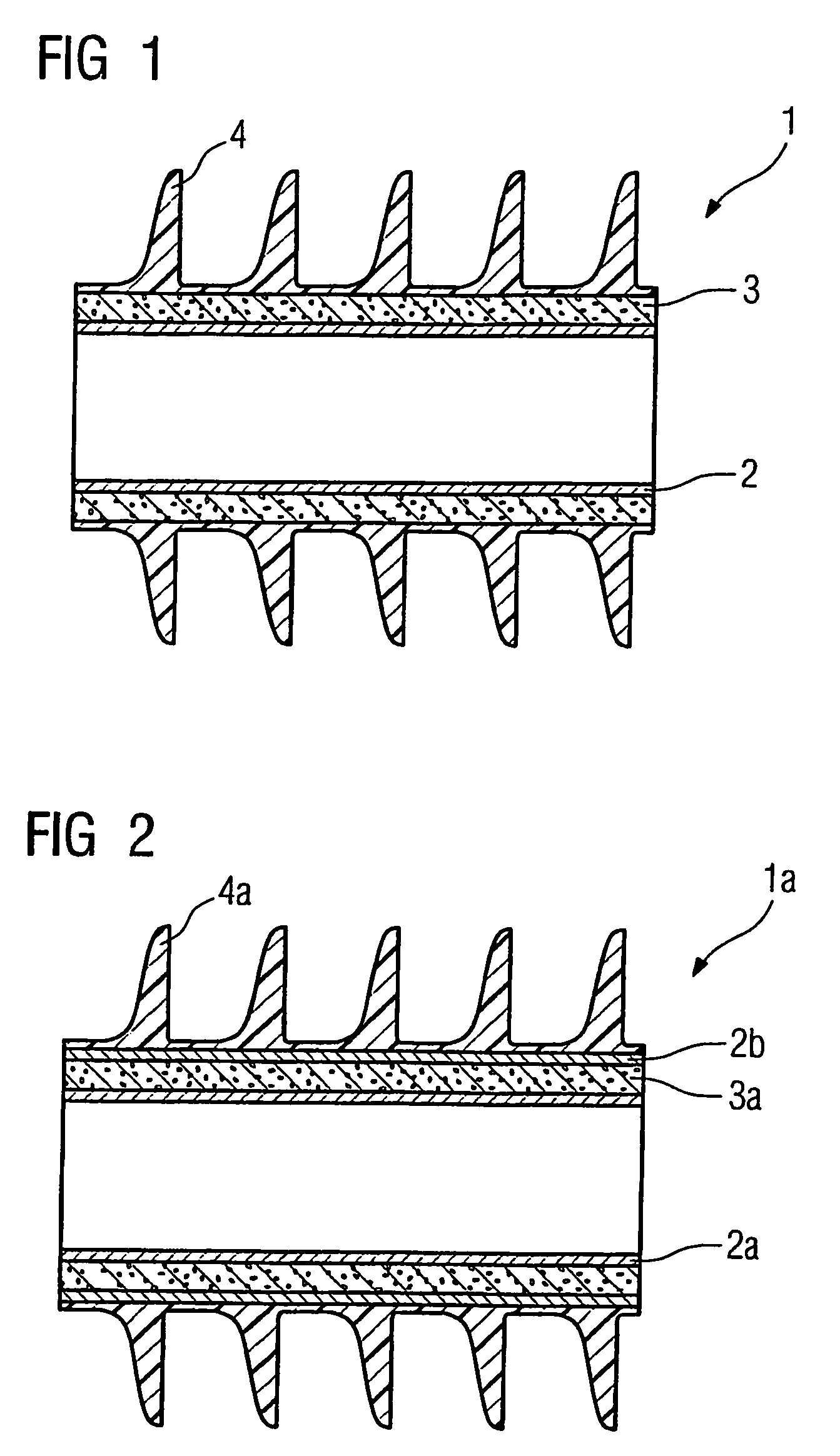
[0014]In particular the design of
composite insulators allows for the very simple introduction of insulating regions. In general, the
composite insulators have a mechanically stabilizing element. This element may be, for example, an inner tube. The further
layers for ensuring sufficient
dielectric strength are then applied to this tube. Such
layers are, for example,
silicone layers which have a protective
coating on the outer surface. It is particularly advantageous here to arrange the thermally insulating layer between the inner tube and the respective
surface layer. As a result, the interior space remains free from thermally insulating sections and can be used in the usual manner. The outer surface is also retained in terms of its structure, with the result that its electrical and mechanical properties are not impaired by the insulating region. The thermally insulating region can in this case be completely sheathed by the inner tube and the outer
surface layer. For this purpose, the
surface layer may be in the form of a
silicone protective
coating, for example, which conforms to the shape of the inner tube even at the front ends of the thermally insulating layer completely around this layer. This allows for the use of various materials for the thermally insulating region since it is largely protected from external influences. It is possible, for example, to use foamed plastics such as
polyurethane or other polymers. The use of insulating gases for foaming purposes in this case makes it possible for the cavities produced in the foam to be designed to be dielectrically stable. It is possible to use, for example,
nitrogen or
sulfur hexafluoride as the insulating gas.
[0016]The use of two tubes which are positioned coaxially with respect to one another makes it possible to use the tubes themselves as the shell for the thermally insulating region. As a result, particularly simple methods can be used for introducing the thermally insulating region into the annular gap formed between the tubes. In addition, the insulating material can be selected such that the two tubes are fixed in position in relation to one another via the
thermal insulation. This results in a layered body, which has a high
mechanical stability owing to the tubes and a good
thermal insulation capacity owing to the thermally insulating section between the tubes. Given a suitable choice of the thermally insulating material, the
mechanical stability of the connected tubes can additionally be increased given a
low mass. With such an arrangement, there are virtually no restrictions as regards previously used manufacturing methods for insulators. Furthermore, a fixed tubular structure is provided towards the interior space. A fixed tubular structure is likewise provided at the surface regions to be applied on the outside.

