Optical head and data processing apparatus including the same

a data processing apparatus and optical head technology, applied in the field of optical heads, can solve the problems of not being able to apply to an optical head that adopts a one-beam method using no sub-beams or to an optical drive including such an optical head, the three-beam method is much more complicated in configuration and processing than the one-beam method, and it is difficult to achieve a sufficiently high snr in such a situation. , to achieve the effect of high s

Inactive Publication Date: 2008-10-28
PANASONIC CORP
View PDF24 Cites 4 Cited by
  • Summary
  • Abstract
  • Description
  • Claims
  • Application Information

AI Technical Summary

Benefits of technology

[0015]In order to overcome the problems described above, preferred embodiments of the present invention provide an optical head, which can perform a layer sensing process without depending on the tracking error detecting method and with signals having high SNR used, and an optical data processing apparatus including such an optical head.

Problems solved by technology

However, this layer sensing method is supposed to use sub-beams by the three-beam method, and cannot be applied to an optical head that adopts a one-beam method using no sub-beams or to an optical drive including such an optical head.
The three-beam method is much more complicated in configuration and processing than the one-beam method.
Thus, it is difficult to achieve a sufficiently high SNR in such a situation.

Method used


Image

  • Optical head and data processing apparatus including the same
  • Optical head and data processing apparatus including the same
  • Optical head and data processing apparatus including the same

Examples


embodiment 1

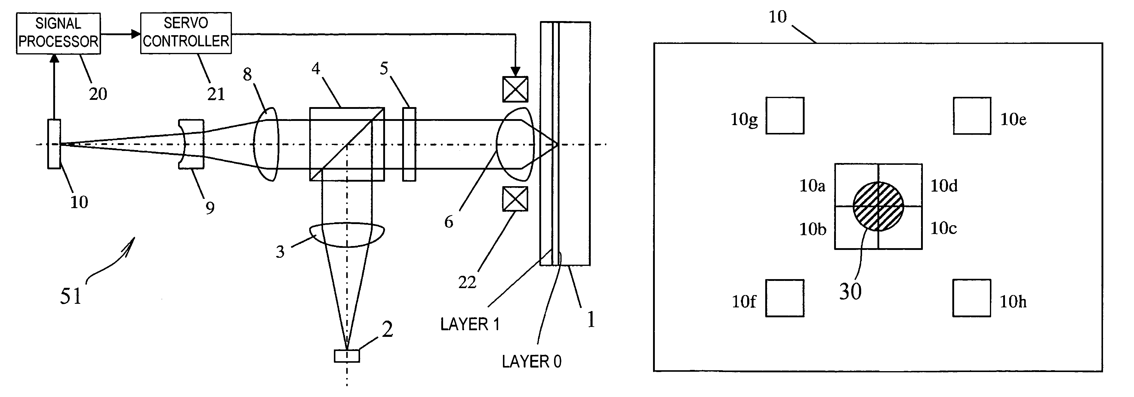
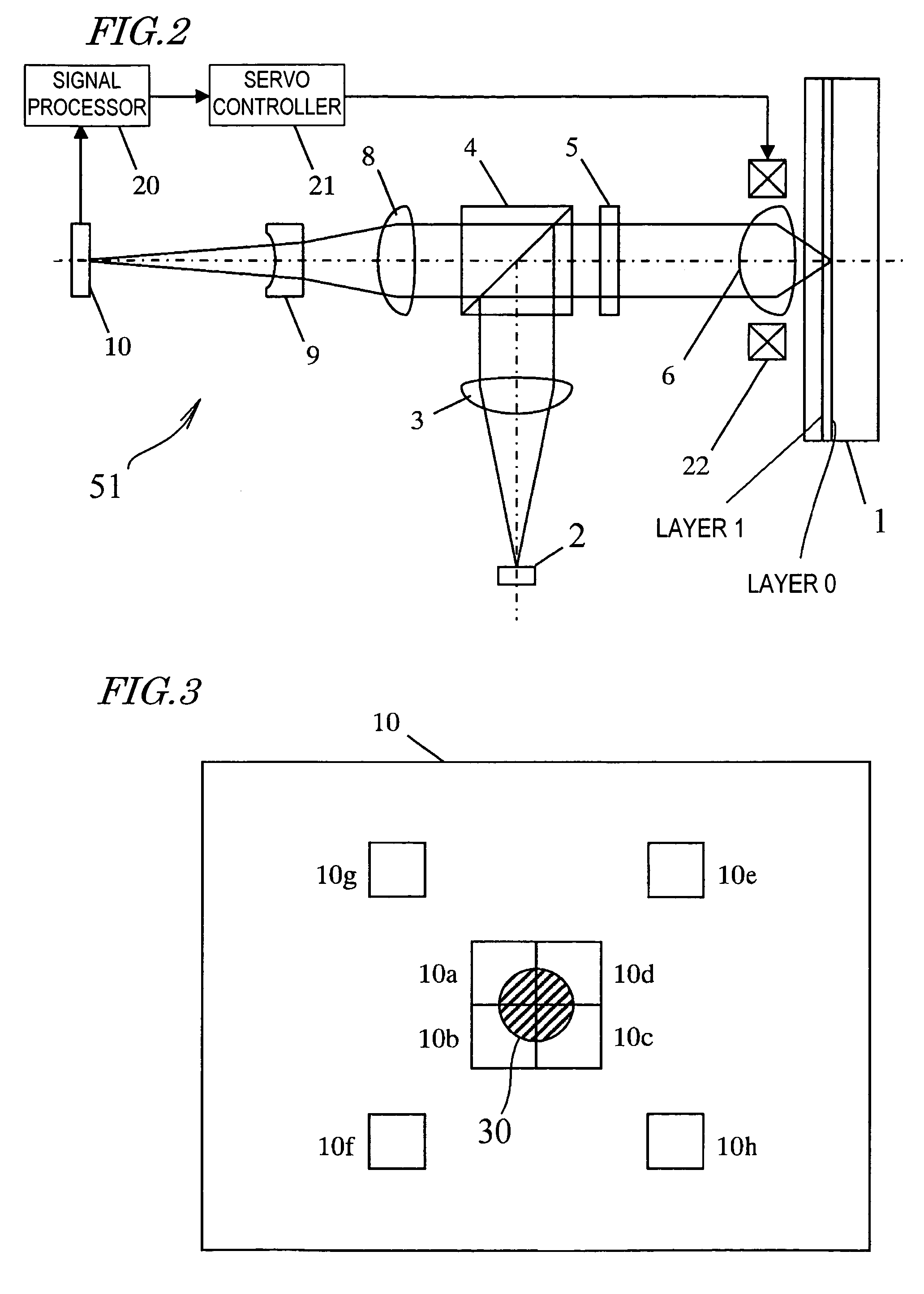
[0070]FIG. 2 shows a configuration for an optical disc drive 51 according to a first specific preferred embodiment of the present invention. The optical disc drive 51 reads and / or writes data from / on Layer 0 and / or Layer 1 by irradiating the optical disc 1 with light from under Layer 1.

[0071]The optical disc drive 51 preferably includes a semiconductor laser light source 2, a collimator lens 3, a beam splitter 4, a quarter wave plate 5, an objective lens 6, a detector lens 8, an anamorphic lens 9, a light detector 10, a signal processor 20, a servo controller 21 and an actuator coil 22. The optical disc 1 is normally removable and does not belong to the optical disc drive 51 but is shown in FIG. 2 for convenience sake. It should be noted that the optical disc drive 51 actually includes various other hardware components such as a spindle motor for rotating the optical disc 1, a modulator and demodulator for reading and / or writing data, and an error corrector. However, only main compo...

embodiment 2

[0106]FIG. 10 illustrates a configuration for an optical disc drive 52 according to a second specific preferred embodiment of the present invention. The optical disc drive 52 basically has the same components as the optical disc drive 51 shown in FIG. 2. However, as in FIG. 4, the illustration of some of those components is omitted from FIG. 10. Also, as in the first preferred embodiment described above, an optical head is made up of the light source, focusing optical system, detecting optical system and light detector.

[0107]Unlike the optical disc drive 51 of the first preferred embodiment described above, the optical disc drive 52 of this second preferred embodiment is designed such that when the focal spot of the laser beam is located near Layer 1, the light reflected from Layer 0 is focused before entering the anamorphic lens 9. This design is adopted such that astigmatism is produced in mutually different directions in the light reflected from Layer 1 when the focal spot is loc...

embodiment 3

[0119]FIG. 12A illustrates a configuration for an optical disc drive 53 according to a third specific preferred embodiment of the present invention. FIG. 12B illustrates the anamorphic lens 9 and its surrounding portion 60 on a larger scale. The optical disc drive 53 basically has the same components as the optical disc drive 51 shown in FIG. 2. However, as in FIG. 4, the illustration of some of those components is omitted from FIG. 12A. Also, as in the first preferred embodiment described above, an optical head is made up of the light source, focusing optical system, detecting optical system and light detector.

[0120]In the optical disc drive 53 of this preferred embodiment, an opaque region 12 is provided on the anamorphic lens 9 so as to cut off a portion of the light being transmitted through the anamorphic lens 9 as shown in FIG. 12B. Also, the optical disc drive 53 is designed such that when the focal spot is located near Layer 1, the light reflected from Layer 0 is substantial...


PUM

PropertyMeasurementUnit
depthaaaaaaaaaa
depthaaaaaaaaaa
wavelengthaaaaaaaaaa

Abstract

An optical data processing apparatus reads and/or writes data from/on a data storage medium, in which first and second data storage layer are stacked, by radiating light from the second layer. The processor includes: a light detector including at least one photodetector for generating a light quantity signal; a detecting optical system for guiding first and second reflected light beams from the first and second layers to the light detector; and a signal processor for generating a layer sensing signal from the light quantity signal and determining, by the layer sensing signal, whether the focal spot is now located near the first layer or the second layer. The detecting optical system includes an optical element that produces astigmatism to the first and second reflected beams. The light detector includes, as the at least one photodetector, a layer sensing photodetector arranged so as to include respective areas of the light detector where the second reflected beam is incident when the focal spot is located near the first layer and where the first reflected beam is incident when the focal spot is located near the second layer.

Description

BACKGROUND OF THE INVENTION[0001]1. Field of the Invention[0002]The present invention relates to an optical head for optically reading and / or writing data from / on an optical data storage medium (such as an optical disc) including multiple data storage layers and also relates to an optical data processing apparatus including such an optical head.[0003]2. Description of the Related Art[0004]Various techniques have been developed in order to increase the storage capacity of an optical disc in one way or another. For example, as some people proposed it, the storage density or capacity of an optical disc is increased either by shortening the wavelength of a laser beam for use to read and write data from / on the disc or by increasing the numerical aperture (NA) of an objective lens for focusing the laser beam on the disc. Others proposed that the storage capacity be increased by providing multiple data storage layers, on which data can be written, for a single optical disc. In this techniq...

Claims


Application Information

Patent Timeline
Patent Type & Authority Patents(United States)
IPC IPC(8): G11B7/125G11B7/00G11B7/085G11B7/09G11B7/13G11B7/135
CPCG11B7/1378G11B7/1381G11B7/08511G11B7/0909G11B7/131G11B2007/0013
Inventor YAMASAKI, FUMITOMONAKAMURA, TOHRU
Owner PANASONIC CORP
Why Eureka
Try Eureka