
Close-conforming vehicle floor tray with reservoir

a technology for vehicle floor mats and reservoirs, which is applied in the direction of roofs, vehicular safety arrangments, and mechanical means, etc., can solve the problems of difficult fitting of such a tray to the complex three-dimensional surface of the vehicle foot well, and the occupants of the vehicle have a tendency to push around the floor mats with their

Active Publication Date: 2008-11-04
MACNEIL IP
View PDF13 Cites 28 Cited by
  • Summary
  • Abstract
  • Description
  • Claims
  • Application Information

AI Technical Summary

Benefits of technology

[0020]In a further aspect of the invention, a vehicle floor tray or mat according to the invention is made of three layers, wherein a top layer and a bottom layer have composition(s) distinct from the central layer, and wherein at least one of the shear strength per cross-sectional area, tensile strength per cross-sectional area and stiffness per cross-sectional area is greater than any one of the layers from which the tray or mat is composed. It has been found that a triextruded vehicle mat or floor tray according to the invention exhibits a tensile strength at yield, a tensile stress at break, a tensile modulus, a shear strength and a flexural modulus (stiffness) which are superior to either a polyolefin-dominated single extrusion or a thermoplastic elastomer-dominated single extrusion. The triextrusion tray demonstrates these enhanced physical properties while at the same time affording an enhanced coefficient of friction to the feet of the occupant and improved tactile properties. By presenting such a surface to the shoe of the driver or passenger, the footing of the driver or passenger will be more sure and comfortable.
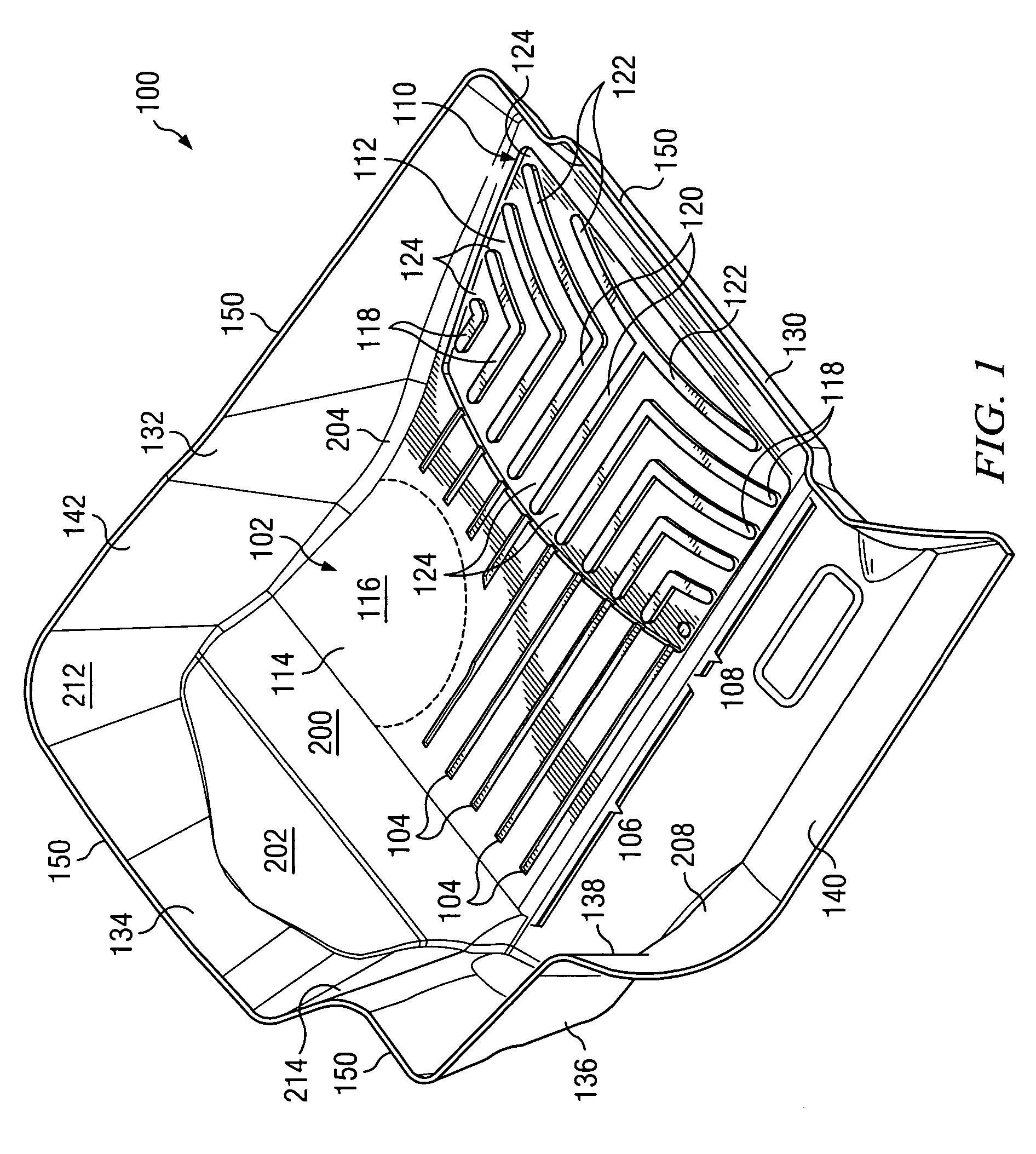
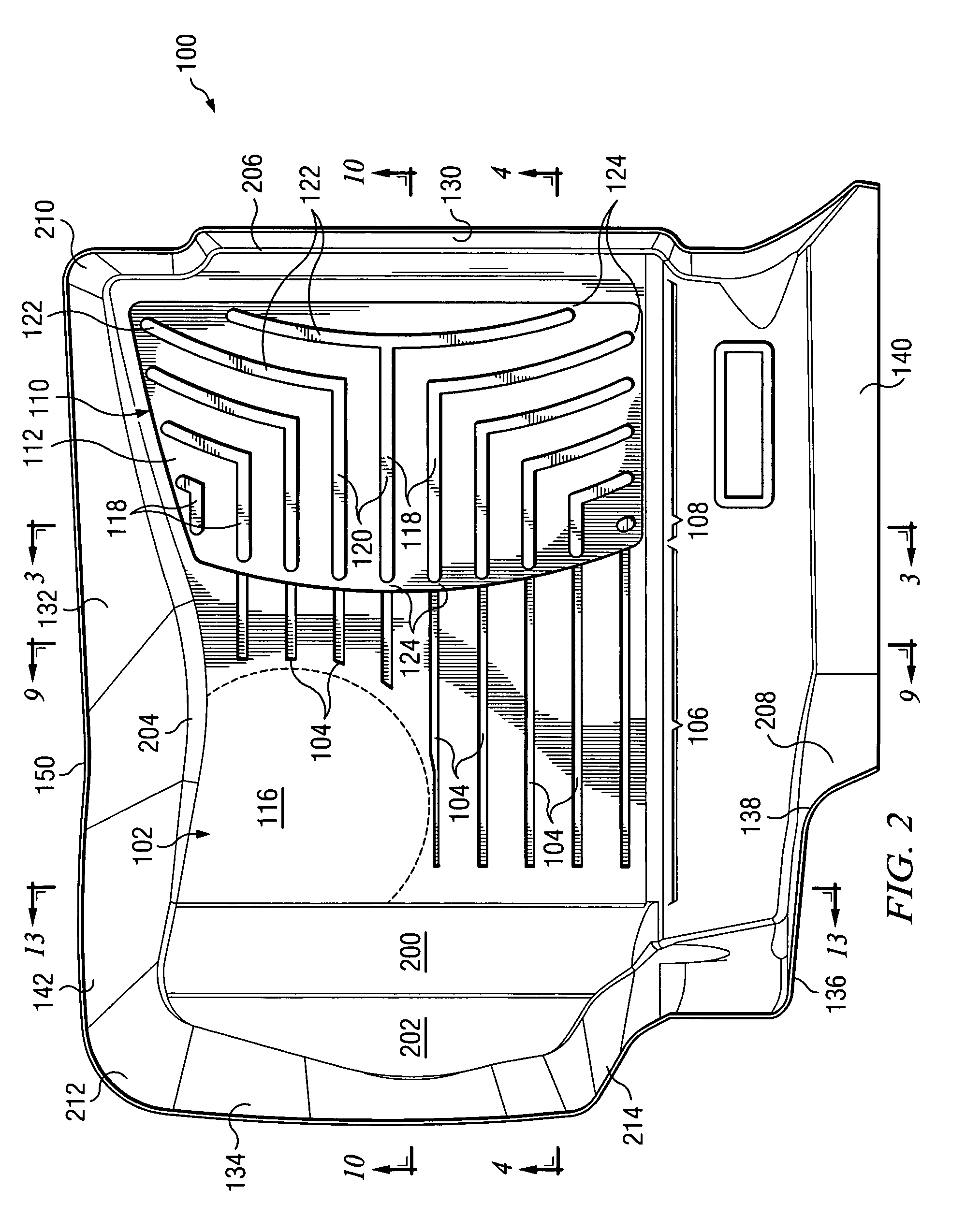
[0023]In a still further aspect of the invention, a top margin of a vehicle floor tray is substantially coplanar on at least two upstanding sidewalls thereof. Preferably, the top margin of the tray is substantially coplanar through three or even four continuous upstanding sidewalls. This eases the design of the floor tray, increases hoop strength and assures that all upstanding surfaces of the vehicle foot well will receive adequate protection from muddy footwear. In a particularly preferred embodiment, the plane of the top margin is forwardly and upwardly tilted relative to a horizontal floor. This provides enhanced protection to the vehicle foot well precisely in the place where muddy footwear are likely to be, near the accelerator, brake and clutch pedals or the firewall, while allowing movement of the seat. In a preferred embodiment, the tray is at least four inches (10.1 cm) deep at its deepest part.
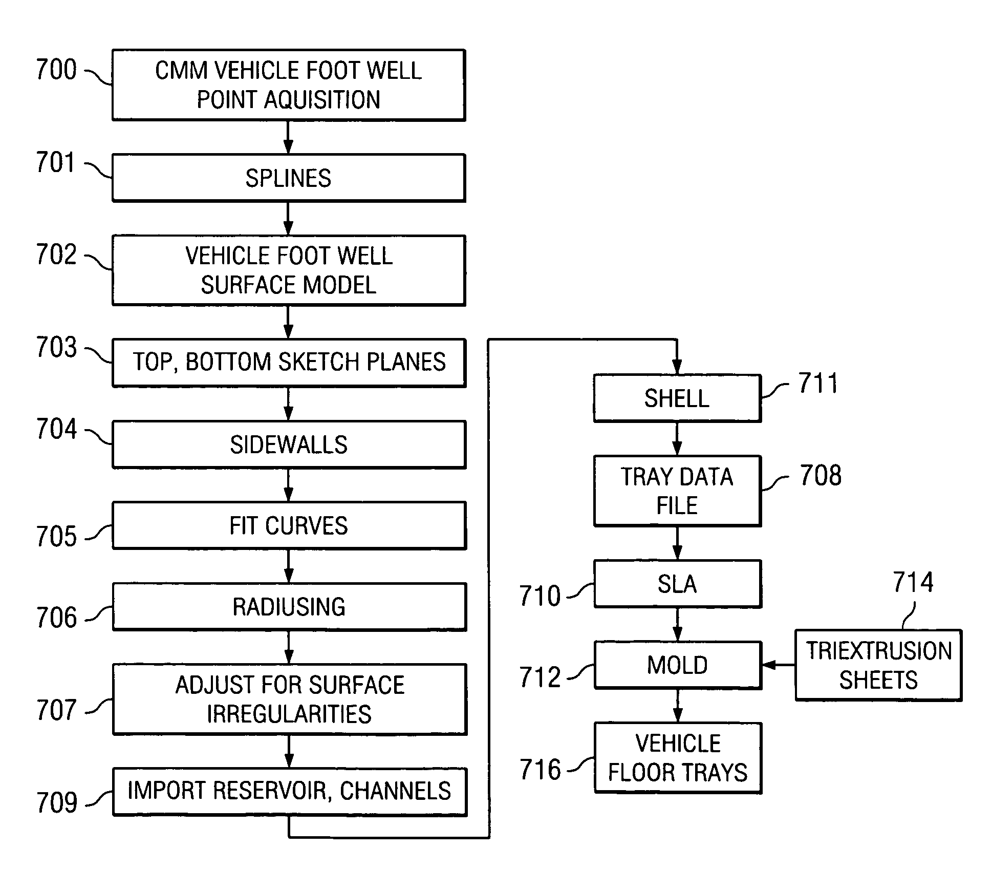
[0024]In a still further aspect of the invention, the above mentioned tight tolerances are made possible by a novel vehicle floor tray manufacturing method and system. In a first step according to the invention, points on a surface of the vehicle foot well are digitally measured with a coordinate measuring machine (CMM). These points are stored in a computer memory. A foot well surface is generated which includes these points, preferably by connecting linear groups of the points together by using B-splines, and lofting between the B-splines to create areal portions of the foot well surface. Using this typically complex three-dimensional, predominately concave surface, which may have several concavely and convexly curved portions, a corresponding, substantially convex outer or lower floor tray surface is created such that in many regions, the distance between the outer surface of the tray and the surface of the foot well is no more than about one eighth of an inch (0.317 cm), insuring a snug fit.

Problems solved by technology

This has caused a problem, in that the occupants of a vehicle have a tendency to push around the floor mats with their feet.
The floor mats end up not being centered on the area protected, or pushed up so as to occlude the gas, brake or clutch pedals, or bunched up or folded over - all undesirable conditions.
Conventional vehicle floor trays try to fit into these three-dimensional cavities, but so far their fit to the surfaces that they are supposed to protect has been less than optimum.
Fitting such a tray to the complex three-dimensional surface of a vehicle foot well has proven to be difficult, and many products currently in the marketplace have limited consumer acceptance because of their loose fit inside the foot well.
There is often, and in many places, a considerable space between the exterior wall of these conventional trays and the interior surface of the foot well.
This causes the wall to noticeably deform when the occupant's foot contacts it.
Vehicle owners have a tendency to dislike floor trays which rattle, deform, shift and flop about.
This casting necessitates substantial and uniform compression of the vehicle carpet pile and subsequently causes an inexactness of fit.
Floor trays produced by this process also have been relatively shallow, perhaps due to limitations inherent in using a casting fluid which then solidifies.
If there is enough of it, it will leak off of the floor mat and stain the carpeting of the foot well that the mat was meant to protect.
But including such a reservoir within a floor tray that otherwise has an acceptable fit to the three-dimensional surface of a vehicle foot well has not yet been done, since there are problems in incorporating a three-dimensional liquid-holding vessel into a product that ideally conforms, on its lower surface, to the surface of the foot well.
Further, a reservoir which collects drip water from a large surface, such as a vehicle floor tray, will exhibit more problems in keeping the collected fluid from sloshing about in a moving vehicle than a reservoir in a mat of more limited area.

Method used


Image

  • Close-conforming vehicle floor tray with reservoir
  • Close-conforming vehicle floor tray with reservoir
  • Close-conforming vehicle floor tray with reservoir

Examples


example 1

[0096]These tests determined static and kinetic coefficients of friction of a sheet of triextrusion material with respect to an object meant to emulate an typical occupant shoe outsole. This “shoe” was composed of Shore A Durometer 60 neoprene rubber, formed as a “sled” measuring 2.5 in. (6.35 cm)×2.5 in. (6.35 cm)×0.238 in. (0.605 cm). The “shoes” were drawn across an upper, textured surface of a 0.120 in. (0.305 cm) triextrusion sheet formed according to a preferred embodiment of the invention and measuring 4 in. (10.2 cm)×12 in. (30.5 cm), the test performed according to the procedure set forth in ASTM D 1894-01. The triextrusion sheet had, as its top layer, a blend of 75 wt. pct. VYRAM® Grade 101-75 / 25 wt. pct. HMPE. The core layer was 75 wt. pct. HMPE / 25 wt. pct. VYRAM® Grade 101-75. The bottom layer was a blend of 25 wt. pct. HMPE / 75 wt. pct. VYRAM® Grade 101-75. The bottom and top layers each comprised about 12.5% of the sheet thickness while the middle core layer comprised a...

example 2

[0098]Five neoprene rubber “sleds” fabricated as above were drawn across a 4 in. (10.1 cm)×12 in. (30.5 cm) sheet of a single-extrusion 75 wt. pct. HMPE / 25 wt. pct. VYRAM® Grade 101-75, according to ASTM D 1894-01. Results are tabulated below.

[0099]

SledStaticKineticSledKineticWeightCoefficientLoadWeightCoefficientTest NumberStatic Load (g)(g)of Friction(g)(g)of Friction1157200.10.785162200.10.8102151200.00.755148200.00.7403163200.10.815170200.00.8504146200.10.730148200.10.7405154200.10.770155200.10.775Average0.7710.783Std. Dev.0.0320.047

[0100]The above tests show that with respect to a typical shoe sole composition, a material consisting mostly of a thermoplastic elastomer like VYRAM® exhibits a higher coefficient of friction than a material consisting mostly of a high molecular weight polyolefin.

example 3

[0101]These tests compared the tensile strength of a sheet of triextruded material as above described with a sheet of single-extruded blend of material consisting of 75 wt. pct. VYRAM®, Grade 101-75, and 25 wt. pct. HMPE, and further with a sheet of a single-extruded blend of material of 75 wt. pct. HMPE and 25 wt. pct. VYRAM® Grade 101-75. The tested single-extruded VYRAM®-dominated sheet was approximately 0.070 in. (0.178 cm) thick, while the HMPE-dominated sheet was approximately 0.137 in. (0.348 cm) thick. The triextrusion sheet was about 0.120 in. (0.305 cm) thick. The triextrusion sheet, the single-extruded VYRAM®-dominated sheet and the single-extruded HMPE-dominated sheet were die-cut into samples having an average width of 0.250″0.635 cm). The test performed was according to the ASTM D 638-03 testing standard. A cross-head speed of 20 in. (50.8 cm) / min. was used. The extensiometer was set at 1000% based on 1.0″(2.54 cm) gauge length.

Samples were conditioned at 40 hours at 2...


PUM

PropertyMeasurementUnit
ninety degree angleaaaaaaaaaa
radiusaaaaaaaaaa
total thicknessaaaaaaaaaa

Abstract

A vehicle floor tray is molded from a multiple extrusion thermoplastic polymer sheet such that it has high shear and tensile strength, an acceptable degree of stiffness and a high coefficient of friction on its upper surface. The floor tray design is digitally fitted to a foot well of a particular model of vehicle such that a lower surface of the tray is no more than one-half of an inch from a digitally acquired model of the foot well surface.

Description

RELATED APPLICATIONS[0001]This application is a continuation in part of U.S. patent application No. 10 / 976,441 filed Oct. 29, 2004, now U.S. Pat. No. 7,316,847 the specification and drawings of which are fully incorporated by reference herein.BACKGROUND OF THE INVENTION[0002]Motor vehicles are almost always operated in the out of doors and are frequently parked there. It is therefore very common for their occupants to have wet or muddy feet—if the occupants have not just finished an outdoor activity, at least they have had to walk across a possibly wet, snowy or muddy surface to access their vehicles. For decades, therefore, vehicle owners have been attempting to protect the enclosed interiors of their vehicles (cars, trucks, SUVs) from what they themselves track into them. The conventional solution to this has been to provide a vehicle floor mat which may be periodically removed by the owner and cleaned.[0003]Human beings have a tendency to move their feet around, and foot motion i...

Claims


Application Information

Patent Timeline
Patent Type & Authority Patents(United States)
IPC IPC(8): B21D53/88B21B1/46B23Q17/00B62D25/20G01B5/004B29C48/08B29C48/21B60R21/02
CPCB29C47/0021B60R21/02B29C47/065B29K2021/00B29K2023/06B29K2023/12B29K2055/02Y10T29/49622B60R2021/0213B60R2021/0226Y10T428/2457Y10T29/49771Y10T29/4998B29L2031/3017B29C48/08B29C48/21B33Y80/00B33Y50/00B29C67/00B29C67/0011B29C69/00B32B3/28B32B25/00B32B27/00B60N3/048B29C48/18B32B2605/003B32B2270/00B32B27/08B32B27/32B32B2307/54B32B2307/542B32B2274/00B32B2323/04
Inventor MACNEIL, DAVID F.
Owner MACNEIL IP
Learn More