System, apparatus, and method for determining temperature/thickness of an object using light interference measurements

a technology of light interference and measurement method, which is applied in the direction of measuring devices, instruments, using optical means, etc., can solve the problems of complicated installation process of temperature measuring apparatus, complicated optical fiber layout, etc., and achieve the effect of improving stability of substrate processing apparatus and accurately controlling the process characteristics of substra

Active Publication Date: 2008-11-04
TOKYO ELECTRON LTD
View PDF7 Cites 30 Cited by
  • Summary
  • Abstract
  • Description
  • Claims
  • Application Information

AI Technical Summary

Benefits of technology

[0012]An object of the present invention is to provide a temperature / thickness measuring apparatus and the like, with which the temperatures or the thicknesses of a plurality of measurement targets set so as to face opposite each other can be measured at once without having to form a hole at a measurement target, through which measurement light to be used to measure the temperature / thickness of another measurement target is to pass, while reducing the labor required when installing the temperature / thickness measuring apparatus.

Problems solved by technology

However, the following problems may occur if the temperatures of a plurality of measurement targets disposed so as to face opposite each other, such as the wafer and the electrode plate of the upper electrode, are to be measured.
Since this requires the optical fibers to be laid out from the top and the bottom of the processing chamber to transmit the measurement light beams originating from a single light source, the optical fiber layout becomes very complicated, which is bound to complicate the installation process for the temperature measuring apparatus.

Method used


Image

  • System, apparatus, and method for determining temperature/thickness of an object using light interference measurements
  • System, apparatus, and method for determining temperature/thickness of an object using light interference measurements
  • System, apparatus, and method for determining temperature/thickness of an object using light interference measurements

Examples


first embodiment

[0057](Temperature Measuring Apparatus Achieved in the First Embodiment)

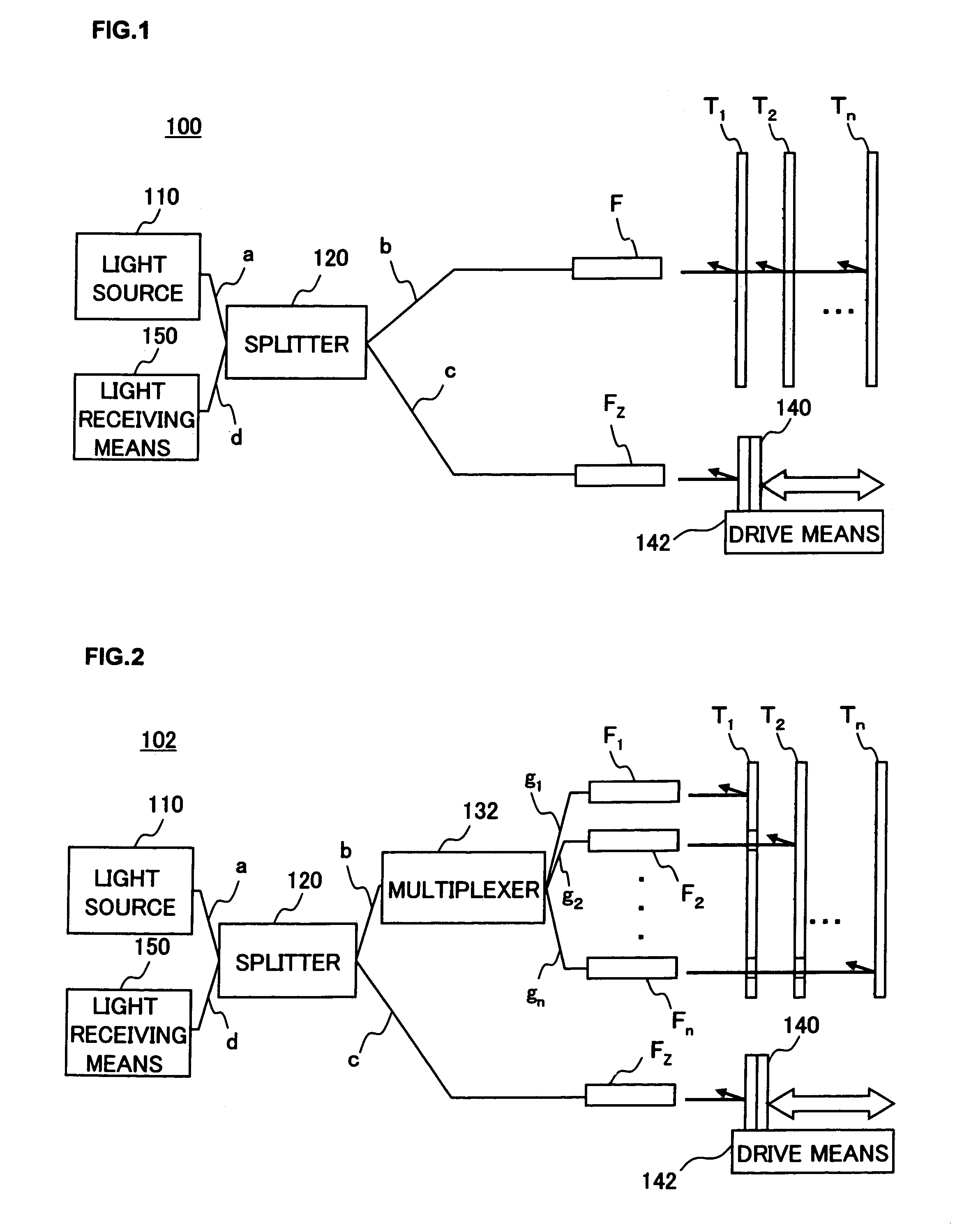
[0058]The temperature measuring apparatus achieved in the first embodiment of the present invention is now explained in reference to drawings. FIG. 1 is a block diagram schematically illustrating the structure adopted in the temperature measuring apparatus achieved in the first embodiment of the present invention. With the temperature measuring apparatus 100 achieved in the first embodiment, the temperatures at a plurality of measurement targets T1 through Tn set so as to face opposite one another, as shown in FIG. 1, can be measured all at once simply by scanning a reference light reflecting means such as a reference mirror just once based upon the principle explained earlier in reference to FIG. 19. The specific structure assumed in this temperature measuring apparatus 100 is described below.

[0059]As shown in FIG. 1, the temperature measuring apparatus 100 comprises a light source 110, a splitter 120 at which ...

second embodiment

[0109](Temperature Measuring System Achieved in Second Embodiment)

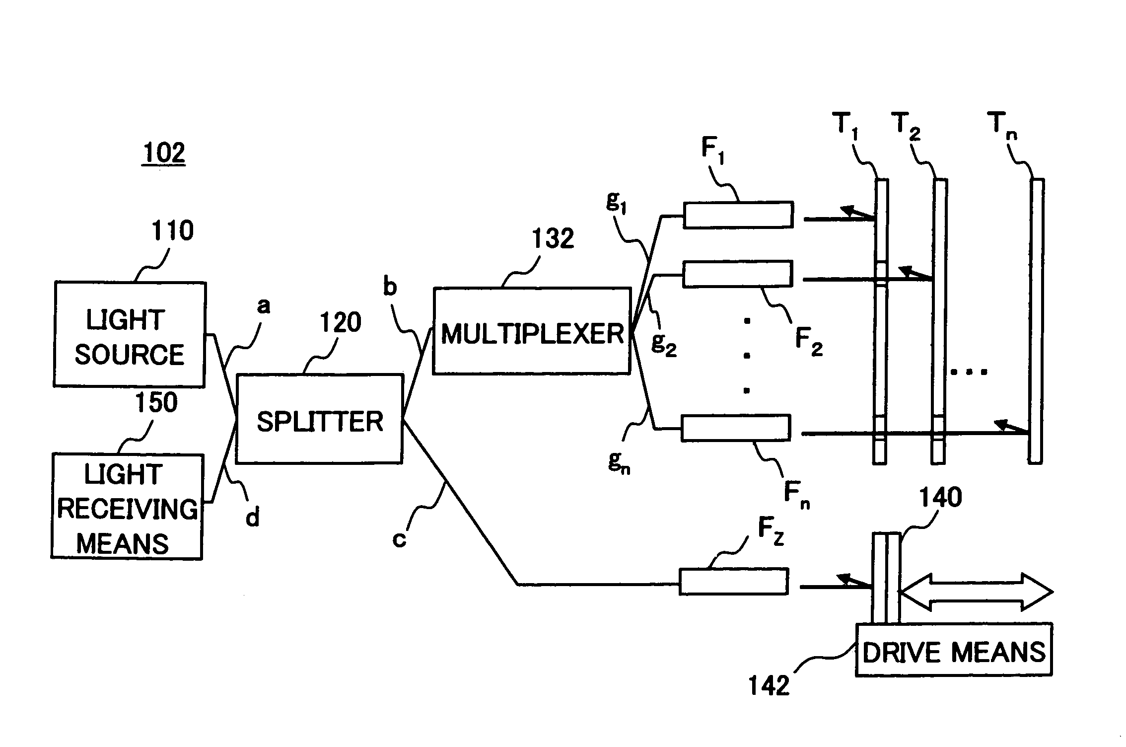
[0110]Next, the temperature measuring system for a substrate processing apparatus achieved in the second embodiment is explained in reference to drawings. The temperature measuring system for a substrate processing apparatus achieved in the second embodiment represents a specific example in which the temperature measuring apparatus in the first embodiment is adopted in conjunction with a substrate processing apparatus. FIG. 5 schematically shows the structure of the temperature measuring system achieved in the second embodiment. An explanation is given in reference to the embodiment on an example in which the present invention is adopted in the measurement of the temperatures at two temperature measurement targets T1 (e.g., an electrode plate Tu of the upper electrode) and T2 (e.g., a wafer Tw) set so as to face opposite each other in the substrate processing apparatus such as a plasma etching apparatus.

[0111]The temp...

third embodiment

[0129](Temperature Measuring System Achieved in Third Embodiment)

[0130]In reference to drawings, the temperature measuring system for a substrate processing apparatus achieved in the third embodiment is explained. The temperature measuring system in the third embodiment is an improvement over the temperature measuring system in the second embodiment in that the distance over which the reference mirror is required to move is further reduced.

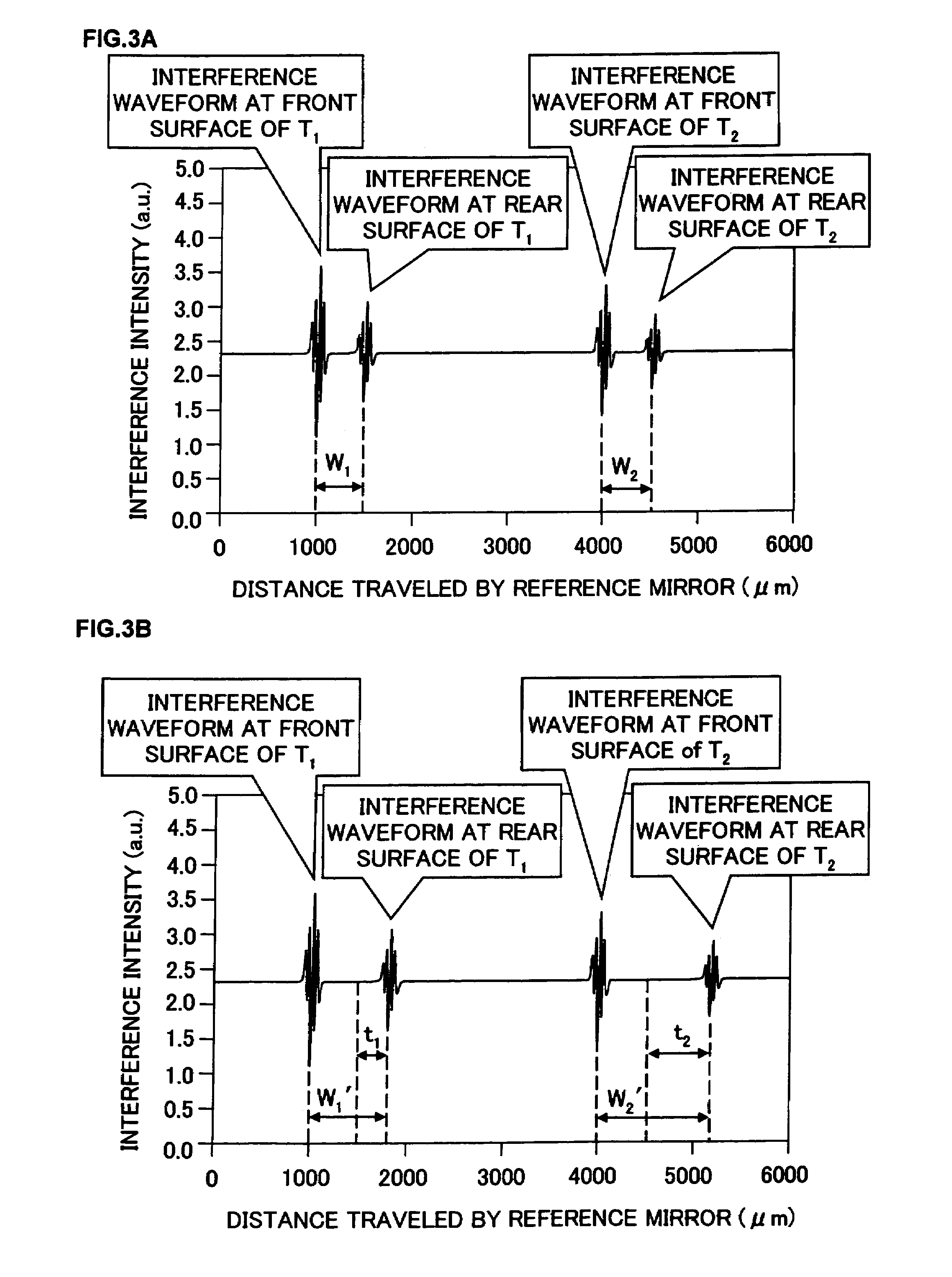
[0131]Namely, since the electrode plate Tu of the upper electrode 350 and the wafer Tw, equivalent to the measurement targets T1 and T2, undergoing the measurement in the temperature measuring system in the second embodiment are distanced from each other over a gap and accordingly, the interference waveforms of the interference manifested by the measurement light and the reference light in correspondence to the electrode plate Tu of the upper electrode 350 and the interference waves of the interference manifested by the measurement light and the r...


PUM


Abstract

A measuring apparatus including a light source that emits light with a wavelength that allows the light to be transmitted through and reflected at each measurement target, a splitter that splits the light from the light source into measurement light and reference light, a reference mirror at which the reference light from the splitter is reflected, a mechanism for driving the reference mirror to adjust the optical path length of the reference light reflected from the reference mirror and a mechanism for measuring the interference of the reference light reflected from the reference mirror as the reference light from the splitter is radiated toward the reference mirror and measurement beams reflected from a plurality of measurement targets as the measurement light from the splitter is radiated toward the measurement targets so as to be transmitted through the measurement targets.

Description

CROSS REFERENCE TO RELATED APPLICATIONS[0001]This document claims priority to Japanese patent application No. 2005-005309, filed Jan. 12, 2005 and U.S. Provisional Application No. 60 / 648, 691, filed Feb. 02, 2005, the entire contents of which are hereby incorporated by reference.FIELD OF THE INVENTION[0002]The present invention relates to a temperature / thickness measuring apparatus, a temperature / thickness measuring method, a temperature / thickness measuring system, a control system and a control method with which the temperature or thickness at the front surface, the rear surface, an inner layer or the like of a measurement target such as a semiconductor wafer or a liquid crystal substrate can be measured accurately.BACKGROUND OF THE INVENTION[0003]It is crucial that the temperature or the like of a substrate processed by, for instance, a substrate processing apparatus, such as a semiconductor wafer (hereafter may be simply referred to as a “wafer”) be measured with a high degree of...

Claims


Application Information

Patent Timeline
Patent Type & Authority Patents(United States)
IPC IPC(8): G01B11/02G01B9/02
CPCG01B11/0675
Inventor SUZUKI, TOMOHIROKOSHIMIZU, CHISHIO
Owner TOKYO ELECTRON LTD
Why Eureka
Try Eureka