
Power takeoff for an electric vehicle

a technology of electric vehicles and power takeoffs, applied in the direction of electric propulsion mounting, transportation and packaging, gearing, etc., can solve the problems of occupying space on the vehicle, “off-the-shelf” components are not readily adaptable for use, and the maintenance of such systems is expensiv

Active Publication Date: 2008-11-11
OSHKOSH CORPORATION
View PDF44 Cites 104 Cited by
  • Summary
  • Abstract
  • Description
  • Claims
  • Application Information

AI Technical Summary

Benefits of technology

The patent describes a power take-off for an electric vehicle that allows for independent control of the speed and torque of the vehicle's electric motor. This is achieved through a gear train and a planetary annulus gear that can move between two positions, with the first position providing a speed that is independent of wheel speed and dependent on the electric motor speed, and the second position providing a speed that is related to both the electric motor speed and the wheel speed. The power take-off can be used to power tools or other equipment mounted on the vehicle. The patent also describes a vehicle support structure and a power storage unit coupled to an electric AC power bus, with a self-contained axle module and an electric motor. The vehicle controller controls the electric motor through signals sent to the motor drive controller, which in turn controls the output shaft. The power take-off allows for independent control of the speed and torque of the electric motor, and can be used to power tools or other equipment mounted on the vehicle.

Problems solved by technology

In other words, “off the shelf” components are not readily adaptable for use in the initial design or ongoing maintenance of such vehicles.
Maintenance of such systems is expensive since specific components must be used.
Such additional components and equipment add cost to the vehicle and take up space on the vehicle.

Method used


Image

  • Power takeoff for an electric vehicle
  • Power takeoff for an electric vehicle
  • Power takeoff for an electric vehicle

Examples


Embodiment Construction

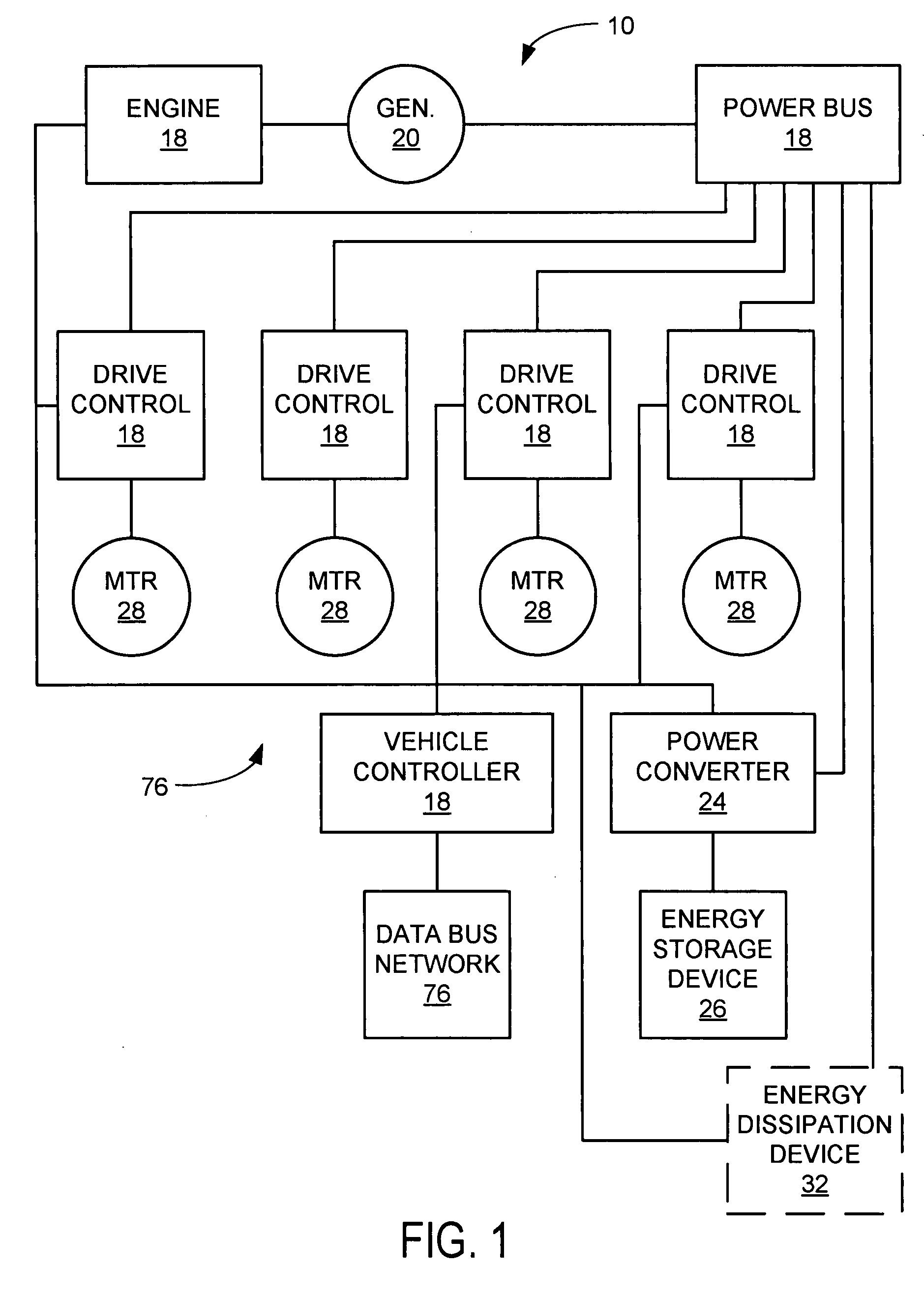
[0012]FIG. 1 is a schematic diagram of an electric vehicle 10 according to an exemplary embodiment. An electric vehicle is a vehicle that uses electricity in some form or another to provide all or part of the propulsion power of the vehicle. This electricity can come from a variety of sources, such as stored energy devices relying on chemical conversions (batteries), stored electrical charge devices (capacitors), stored energy devices relying on mechanical stored energy (e.g. flywheels, pressure accumulators), and energy conversion products. A hybrid electric vehicle is an electric vehicle that uses more than one sources of energy, such as one of the electrical energy storage devices mentioned above and another source, such as an internal combustion engine. By having more than one source of energy some optimizations in the design can allow for more efficient power production, thus one can use power from different sources to come up with a more efficient system for traction. The elec...


PUM


Abstract

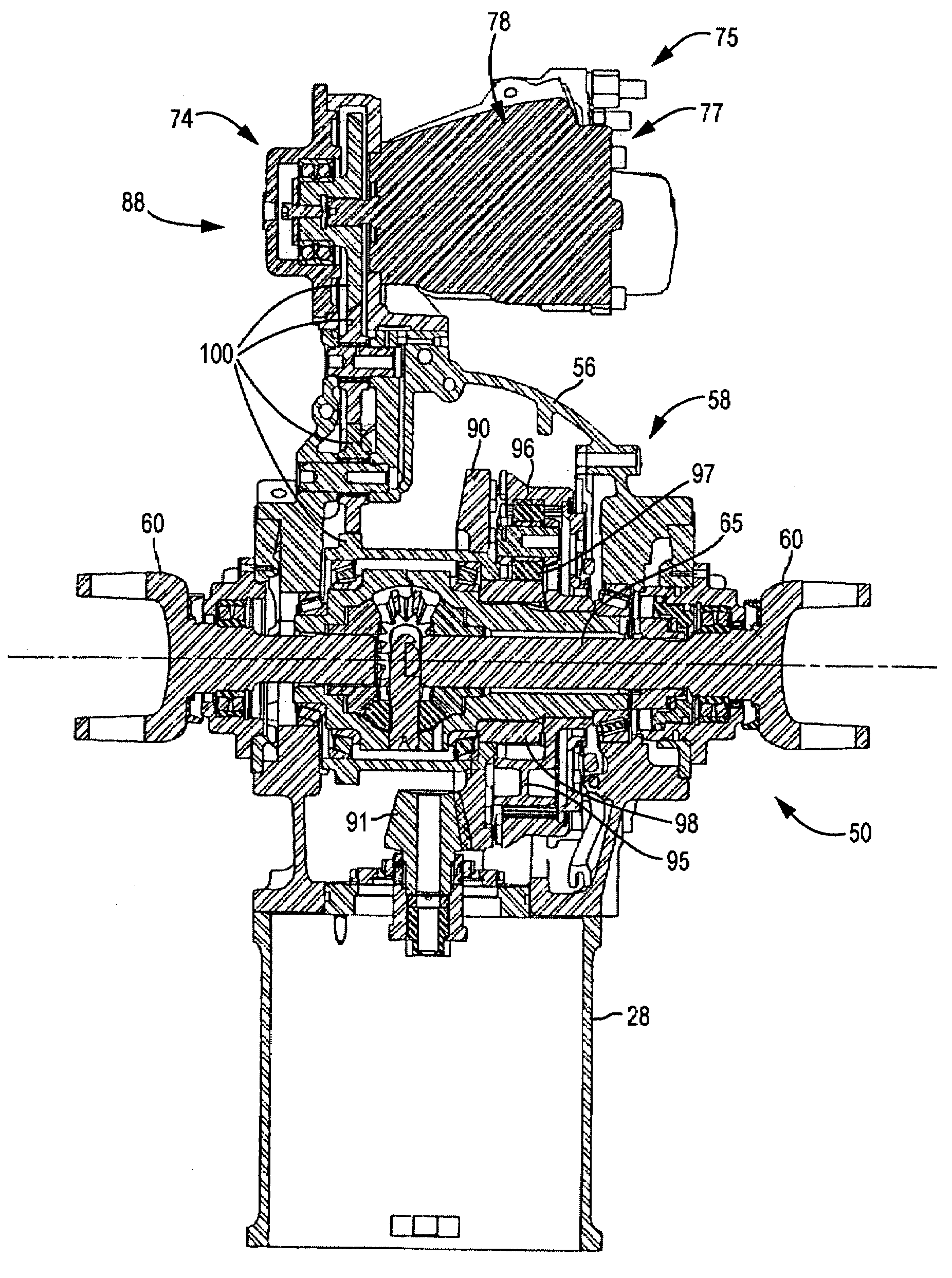
A power take-off for an electric vehicle. The power take-off includes a variable speed electric motor for driving at least one wheel of the vehicle. A transmission, including a neutral state, coupled to the electric motor. An auxiliary output shaft is coupled to the transmission. When the transmission is in the neutral state, the auxiliary output shaft will operate at a speed independent of wheel speed and dependent on the electric motor speed. When the transmission is operably engaged in other than the neutral state, the auxiliary output shaft will operate at a speed related to both the electric motor speed and the wheel speed.

Description

FIELD[0001]The present invention relates generally to hybrid electric vehicles, and more particularly to a power take-off coupled to an axle for an electric vehicle.BACKGROUND[0002]In a conventional electric vehicle, a prime mover such as a diesel engine, is used to drive an electric generator or alternator which supplies electric current to a plurality of electric motors. The electric motors typically are coupled to wheel sets, in line, on the vehicle. The vehicles that utilize this type of hybrid electric motors are typically railroad locomotives.[0003]The prime mover drives the generator / alternator that typically produces an AC current that is then fully rectified with resulting DC current and voltage being distributed to current converters coupled to the traction motors. Such systems are highly integrated with each of the components typically designed and manufactured to operate with the other components in the overall system. In other words, “off the shelf” components are not r...

Claims


Application Information

Patent Timeline
Patent Type & Authority Patents(United States)
IPC IPC(8): B60K17/28B60L50/30
CPCB60K6/46B60K17/28B60Y2200/24Y02T10/6217Y02T10/70Y02T10/62
Inventor MORROW, JON J.SCHIMKE, MARTINYAKES, CHRISTOPHER K.
Owner OSHKOSH CORPORATION
Learn More