Portable range extender with autonomous control of starting and stopping operations

a technology of autonomous control and range extension, which is applied in the direction of hybrid vehicles, electric generator control, engine starters, etc., can solve the problems of inconvenient use and hybrid vehicles present challenges to be addressed, and achieve the effects of accelerating shaft rotation, minimizing emissions, and maximizing fuel economy

Inactive Publication Date: 2008-11-11
BLUWAV SYST LLC
View PDF91 Cites 31 Cited by
  • Summary
  • Abstract
  • Description
  • Claims
  • Application Information

AI Technical Summary

Benefits of technology

[0007]The present invention fulfills the above described needs, at least in part, by provision of a portable range extender capable of supplying electrical energy to a vehicle. The range extender includes a dynamoelectric machine coupled to an internal combustion engine by a shaft. The dynamoelectric machine may be connected to a power source, such as a vehicle battery, to operate as a motor to drive the shaft in rotation when a user initiates starting of the engine. The shaft, and thus the engine, accelerates in rotation while being driven by the dynamoelectric machine, the engine temperature increasing during this warm-up period. The rotational speed and engine temperature are sensed and, when optimal values for each of these parameters are obtained as determined by a dedicated range extender controller, fuel is supplied to the engine and ignition is activated. The engine then acts as a prime mover to further accelerate shaft rotation. As the engine starts only upon optimal speed and temperature conditions, fuel economy is maximized. With a warm start, fuel is burned most efficiently, thus minimizing emissions. As speed increases further, a level is reached at which the dynamoelectric machine can be activated as a generator to provide an electrical current output. At that time the engine has the prime mover capability to support the electrical power generation. The range extender controller outputs a signal in response to speed input for generator activation. When range extender operation is to be terminated, fuel supply to the engine is cut off and ignition is thereafter maintained for a preset period. The fuel remaining in the engine is efficiently burned, thereby avoiding engine backfire and accompanying emission of fumes.
[0008]Although the power generated by the range controller may be applied to charge the vehicle battery and / or drive the vehicle traction motor and other electrical loads, the range controller operations are under the control of an autonomous controller. The range extender and its controlling circuitry are self contained within an enclosure that is independent of a vehicle with which it may be used. An inverter / converter module, coupled to the controller, inverts the direct current supply to alternating current to the dynamoelectric machine when it is in motor operation and converts an alternating current output of the dynamoelectric machine to direct current when it is in generator operation. Also coupled to the controller are an ignition circuit, a fuel supply circuit, speed sensor and temperature sensor. The controller is also provided with user input terminals, thus permitting control of the range extender to be independent of the controller of the vehicle.

Problems solved by technology

Unlike all-electric vehicles, which have a limited travel range and create inconvenience for users by requiring frequent recharging at charging sites, hybrid vehicles do not need to be plugged into an external source of electricity to charge batteries.
However, hybrid vehicles present challenges to be addressed in order to be suitable for widespread implementation.

Method used


Image

  • Portable range extender with autonomous control of starting and stopping operations
  • Portable range extender with autonomous control of starting and stopping operations
  • Portable range extender with autonomous control of starting and stopping operations

Examples


Embodiment Construction

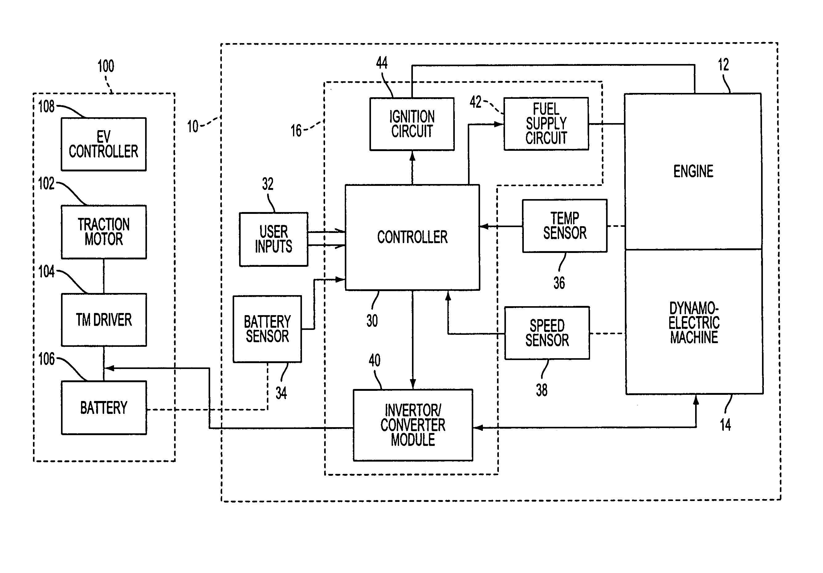
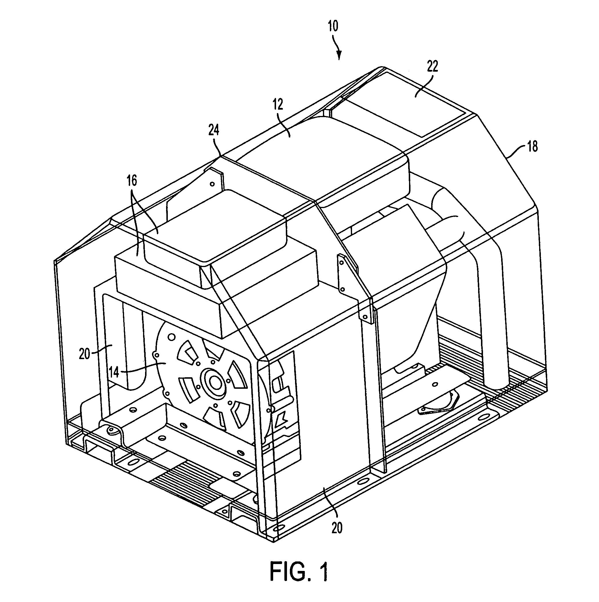
[0016]FIG. 1 exemplifies a portable range extender 10 of the present invention. Prime mover 12, preferably an internal combustion engine, is coupled to dynamoelectric machine 14 by a common shaft. A controller and associated control circuitry are contained in a housing, the control system collectively indicated by reference numeral 16. As described further hereinafter, the control system is effective to control operations of both the engine 12 and the dynamoelectric machine 14. When operation of the range extender is initiated, the dynamoelectric machine 14 is controlled to operate as a motor for starting the engine 12. When prescribed engine conditions are detected, the control system 16 controls the dynamoelectric machine 14 to operate as a generator driven by the engine 12 to produce electrical power supplied to an external load. As a consequence of this control arrangement, there is no necessity for a separate starter motor for the engine, which is commonly provided in conventio...


PUM


Abstract

A portable range extender can be used to supply electrical power to an electric vehicle operable by an electric traction motor. The portable range extender includes an engine, a dynamoelectric machine coupled to the engine by a shaft, an autonomous range extender controller for controlling operations of the range extender independently of a controller for the vehicle, and circuitry associated with the engine and machine. To start operation, electrical energization is applied from the vehicle battery to the dynamoelectric machine for operation as a motor to drive the shaft. As the shaft accelerates, the rotational speed of the shaft and the temperature of the engine are sensed. When the speed and temperature obtain predetermined thresholds, fuel is supplied to the engine and ignition is activated. The engine then operates as a prime mover to drive the shaft in lieu of the machine. After a period of engine prime mover operation, the machine is activated for operation as a generator to provide an electrical current output for charging the battery or supplying energy to the traction motor. When range extender operation is to be stopped, fuel supply is cut off before ignition termination to avoid engine backfire.

Description

FIELD OF THE INVENTION[0001]The present invention relates to electric power supply devices, and more particularly, to portable stand-alone electric power supply devices that can be utilized as range extenders for electric vehicles.BACKGROUND ART[0002]A typical range extender is provided as an integral part of a hybrid electric vehicle to improve its travel range. For example, U.S. Pat. No. 5,264,764 discloses a hybrid electric vehicle comprising an inverter / motor electric drive system, a vehicle controller, a range extender and a traction battery. The inverter / motor electric drive system is composed of an electric motor and an inverter / motor control unit. In response to a hand or foot actuated speed control actuator, a vehicle controller applies a torque command signal to the electric motor to drive the vehicle wheels through a transmission. The range extender, which includes an internal combustion engine and an alternator, is actuated by the vehicle controller to provide electric p...

Claims


Application Information

Patent Timeline
Patent Type & Authority Patents(United States)
IPC IPC(8): F02B63/04F02D29/06H02K7/18H02P9/04B60K1/04B60K6/40B60K6/46B60L50/15F02N11/04F02N11/08F02N11/12
CPCB60K6/40B60K6/46B60L11/02B60L11/126F02N11/04B60L2240/441Y02T10/7077B60W2510/0638B60W2510/0676F02N11/12Y02T10/6217B60L2240/445B60K2006/268B60L50/10B60L50/62Y02T10/62Y02T10/70Y02T10/7072
Inventor CHO, CHAHEE PETERKIM, EUN SHIK
Owner BLUWAV SYST LLC
Why Eureka
Try Eureka