Harmonic mitigating device with magnetic shunt

a technology of mitigating device and magnetic shunt, which is applied in the direction of dc circuit to reduce harmonic/ripple, power conversion system, dc network circuit arrangement, etc., can solve the problems of increasing the voltage total harmonic distortion level, reducing the reliability of power distribution equipment, and reducing the electromagnetic compatibility of loads, so as to reduce the harmonic current flowing, and control the level of magnetic coupling.

Inactive Publication Date: 2008-11-11
1761911 ONTARIO
View PDF6 Cites 12 Cited by
  • Summary
  • Abstract
  • Description
  • Claims
  • Application Information

AI Technical Summary

Benefits of technology

[0015]The present invention overcomes these disadvantages by providing a harmonic mitigating device for connection between the power distribution system and the load, which allows control over the levels of magnetic coupling between different elements of the device while providing all windings on a single core. Control over magnetic coupling is accomplished through the use of magnetic shunts. This allows for the reduction or elimination of the harmonic MMF induced in the line winding of the device, and as a result the reduction of harmonic currents flowing into the power supply system. This further allows for the reduction of the line winding inductance, which in turn reduces the voltage boost of the device under the no-load conditions, reduces the voltage drop at full load conditions and increases the stability of the drive. The invention serves to reduce ripple level in rectifier outputs and buffers transient overvoltages, and a single configuration works with any rectifier type, including SCR bridges.

Problems solved by technology

These harmonic currents create many problems in the power distribution system, including increased voltage total harmonic distortion level, reduced electromagnetic compatibility of the loads, reduced reliability of the power distribution equipment, increased power losses, reduced power factor, and other problems which are well known to those skilled in the art.
1. Power factor corrected (PFC) power supplies: In these systems the rectified current is continually adjusted to smooth the current consumption waveform. PFC's are relatively expensive devices and their applications are limited. Also, PFC's cannot be retrofitted for use with existing power supplies, and are not practical for use with large ASD's.
2. Active filters: These devices inject into the conductors between the power distribution system and the load, harmonic currents having a polarity opposite to those generated by the load, thereby neutralizing harmonic currents flowing into the power distribution system. Active filters have many disadvantages, including high cost, poor reliability. Active filters also are not practical for use with large ASD's.
3. Resonant L-C filters: L-C filters are commonly used in power systems, tuned to different harmonic frequencies to mitigate specific harmonic currents. These devices present many problems which are well known to those skilled in the art, including high cost and the tendency to cause the system to operate with a leading power factor. Further, because L-C filters are non-directional they are easily overloaded by untreated harmonic currents generated by other harmonic sources connected to the power distribution system (for example in a neighboring facility), resulting in overloading and frequent failures of the filter's capacitor bank.
4. AC chokes: In this harmonic mitigating technique reactors are connected in series between the line and the load. This technique is simple, reliable and relatively low cost, however it results in a high voltage drop across the reactors. To reduce the voltage drop one must reduce the choke reactance level, which commensurately reduces the effectiveness of the choke and substantially limits harmonic current mitigation.
The voltage can be boosted by connecting a capacitor bank between the load and the choke, but this frequently causes the system to operate with a leading power factor (especially in the case of light loading).
However, the voltage drop across the choke remains very high.
Thus, large compensating capacitors must be connected between the load and the choke to boost the voltage, which substantially increases the size and cost of the system and causes the system to operate at increased voltage levels during light loading conditions.
However, such systems are typically limited in terms of the number of harmonic orders which can be mitigated, and the degree of harmonic mitigation depends upon the extent to which harmonics produced by the various harmonic sources are identical.
The harmonic currents flowing in the cross-link circuit generate a magneto motive force (MMF), and as a result of magnetic coupling between the blocking element of the filter (the line winding) and the cross-link circuit, the magneto-motive force (MMF) induces harmonic currents in the blocking element that flow directly into the power supply system, increasing the total harmonic current flowing into the power supply system and thereby reducing the effectiveness of harmonic mitigation by the filter.
This causes a substantial voltage boost under no-load conditions, increased voltage drop at full load conditions, and sometimes drive stability problems especially when driving high-inertia loads.
The sets of windings could alternatively be wound on separate cores, however there is a high cost to this both in materials used and in the space occupied by a multiple-core device (known as the ‘footprint’).

Method used


Image

  • Harmonic mitigating device with magnetic shunt
  • Harmonic mitigating device with magnetic shunt
  • Harmonic mitigating device with magnetic shunt

Examples


Embodiment Construction

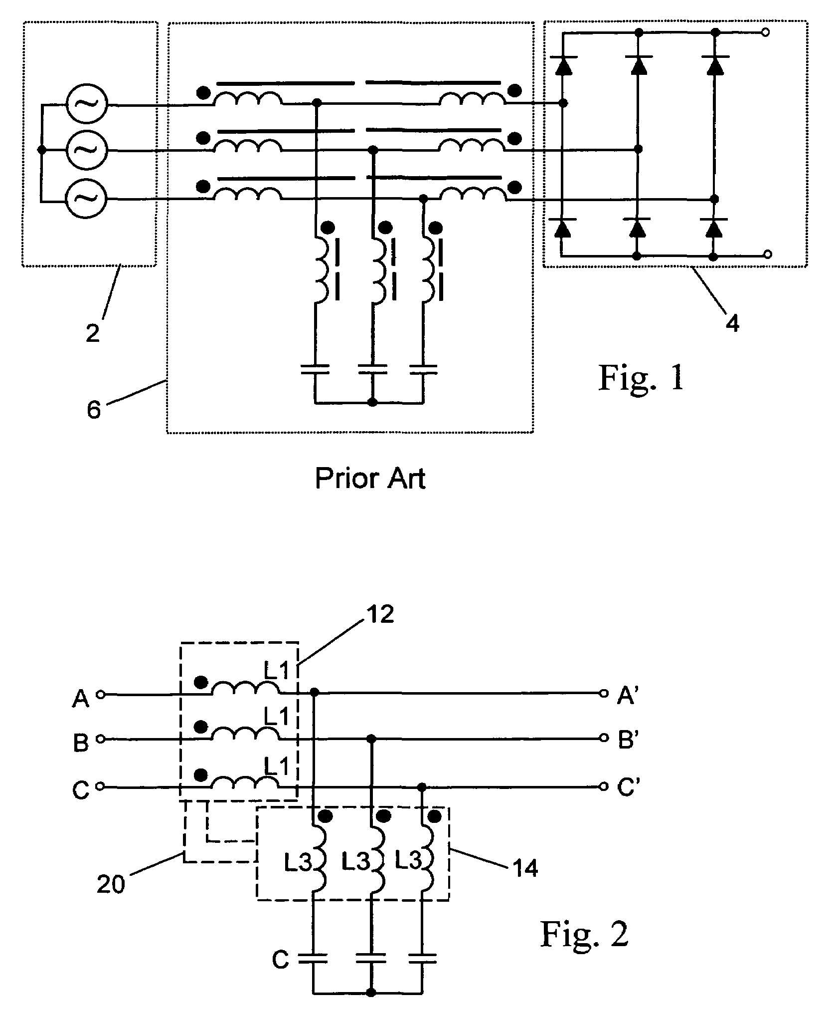
[0034]The harmonic mitigating system of the invention may utilized in a multi-winding reactor having a capacitor bank, similar to that described and illustrated in U.S. Pat. No. 6,127,743 issued Oct. 3, 2000 to Levin et al., which is incorporated herein by reference and illustrated in FIG. 1. In the embodiments of the invention illustrated and described hereafter, the power distribution system 2 may be any AC electrical power source, typically a mains power supply powered by an electrical utility or a local generator. The load 4 typically includes one or more harmonic generating (non-linear) loads, the most common being non-linear loads such as adjustable speed drives, rectifiers etc. The harmonic spectrum of different types non-linear loads may vary, however the device of the invention is suitable for mitigating harmonic currents generated by many different kinds of harmonic generating loads.

[0035]In the prior art harmonic mitigating system 6 illustrated in FIG. 1, described in U.S...


PUM

PropertyMeasurementUnit
non-magnetic gapaaaaaaaaaa
power lossesaaaaaaaaaa
power factoraaaaaaaaaa

Abstract

A harmonic mitigating device for connection between a power distribution system and the load uses a magnetic shunt to control the levels of magnetic coupling between different elements of the device while providing all windings on a single core. This allows for the reduction or elimination of the harmonic MMF induced in the line winding of the device, and as a result the reduction of harmonic currents flowing into the power supply system; and the reduction of the line winding inductance, which in turn reduces the voltage boost of the device under the no-load conditions, reduces the voltage drop at full load conditions and increases the stability of the drive. The invention serves to reduce ripple level in rectifier outputs and buffers transient overvoltages, and a single configuration works with any rectifier type, including SCR bridges.

Description

FIELD OF INVENTION[0001]This invention relates to harmonic mitigating devices for electrical power distribution systems. In particular, this invention relates to a solid state passive harmonic mitigating device for connection between the power distribution system and one or more harmonic-generating loads, to reduce the levels of harmonic currents flowing into the power distribution system.BACKGROUND OF THE INVENTION[0002]Electrical distribution systems, for example for distributing an electrical power supply through a building or industrial facility, are often subjected to harmonic currents generated by non-linear loads such as electronic equipment (including computers, adjustable speed drives (ASD), uninterruptable power supplies (UPS), power rectifiers, etc.) and equipment that uses different kinds of arc processes (including arc discharge lighting systems). These harmonic-generating loads generate various levels of conventional harmonics (5th, 7th, 11th, 13th, 17th, 19th, 23rd, 2...

Claims


Application Information

Patent Timeline
Patent Type & Authority Patents(United States)
IPC IPC(8): H02J1/02H01F27/24
CPCH02J3/01Y02E40/40
Inventor LEVIN, MICHAEL I.HOEVENAARS, ANTHONY H.VOLKOV, IGOR V.
Owner 1761911 ONTARIO
Why Eureka
Try Eureka