Device and method for withdrawing a tubular body part

a tubular body and device technology, applied in the field of medical devices for withdrawing tubular body parts, can solve the problems of cosmetic deformities, pain in legs, medical complications, etc., and achieve the effect of less trauma to surrounding tissu

Inactive Publication Date: 2008-11-25
ANGIODYNAMICS INC
View PDF4 Cites 79 Cited by
  • Summary
  • Abstract
  • Description
  • Claims
  • Application Information

AI Technical Summary

Benefits of technology

[0020]By using a puncture device that also contains a deployable engaging element, the present invention allows the puncture site to be small and causes less trauma to the surrounding tissue.

Problems solved by technology

Symptoms include discomfort, aching of the legs, itching, cosmetic deformities, and swelling.
If left untreated, varicose veins may cause medical complications such as bleeding, phlebitis, ulcerations, thrombi and lipodermatosclerosis.
Varicose veins are caused when those valves become incompetent and can no longer prevent the reflux of blood into the superficial veins.
Because the veins are thin walled and not able to withstand the increased pressure, the veins become dilated, tortuous and engorged.
While providing temporary relief of symptoms, these techniques do not treat the incompetent valves that are the underlying cause of the varicose veins.
Although permanent treatments focus on elimination of reflux, there are drawbacks and complications associated with surgical removal and vein occlusion procedures.
Even with its clinical effectiveness, surgical excision is rapidly becoming an outmoded procedure due to the high costs of treatment and risk of complications from surgery.
In addition, the cosmetic results are often unsatisfactory due to scarring.
Although complications are usually minor, in some rare cases, serious dermal burns, focal numbness, vessel perforations and pulmonary emboli have been reported.
However, drawbacks of the thermal treatment of varicose veins include the high cost of equipment for the generator and disposables as well as the inability to treat all vein sizes.
In addition, the size of the thermal delivery system limits the size of veins that can be treated with this method.
Although the chemical occlusion procedure is a popular treatment option, complications can be severe including skin ulceration, anaphylactic reactions and permanent skin staining.
Treatment is also limited to veins of a particular size range, typically smaller veins.
Other drawbacks include a relatively high recurrence rate due to vessel re-canalization and inability to treat the underlying valve incompetence originating at the saphenous-femoral junction.
As previously described, ultrasound-guided sclerotherapy is often not completely effective in eliminating the reflux source and as a result the treatment may need to be repeated.
The disadvantage of this technique is the size of the incision which causes unnecessary trauma and unsightly scarring.
One main disadvantage of ambulatory phlebectomy as a varicose vein treatment is the relatively long procedure time.
This blind procedure results in inadvertent hooking of other bodily structures such as nerves and can also result in incomplete vein segments being extracted.
These movements can cause trauma to the surrounding tissue and significant post-procedural bruising.
While Suval teaches a design for engaging and removing the vein by using a single instrument, the technique still suffers from the same drawbacks that are present in any ambulatory phlebectomy.
Thus, the phlebectomy procedure using Suval's device and method remains a blind procedure with the inherent risks of inadvertently extracting a nerve or other non-targeted structure.
Since Suval's device cannot precisely target the vein, repeated attempts may be required before the vein is successfully hooked and extracted resulting in extended procedural time.
Perhaps the most serious drawback of ambulatory phiebectomy including the Suval procedure is the risk of inadvertently hooking nerves or other body tissue.
Because nerves and veins are often located in close proximity to each other and often have the same appearance, it is difficult to distinguish a nerve either tactilely or visually when using a traditional phlebectomy hook.
As a result, a nerve may be mistakenly hooked and withdrawn during an ambulatory phlebectomy procedure, resulting in temporary or even permanent nerve damage to the patient.

Method used


Image

  • Device and method for withdrawing a tubular body part
  • Device and method for withdrawing a tubular body part
  • Device and method for withdrawing a tubular body part

Examples


Embodiment Construction

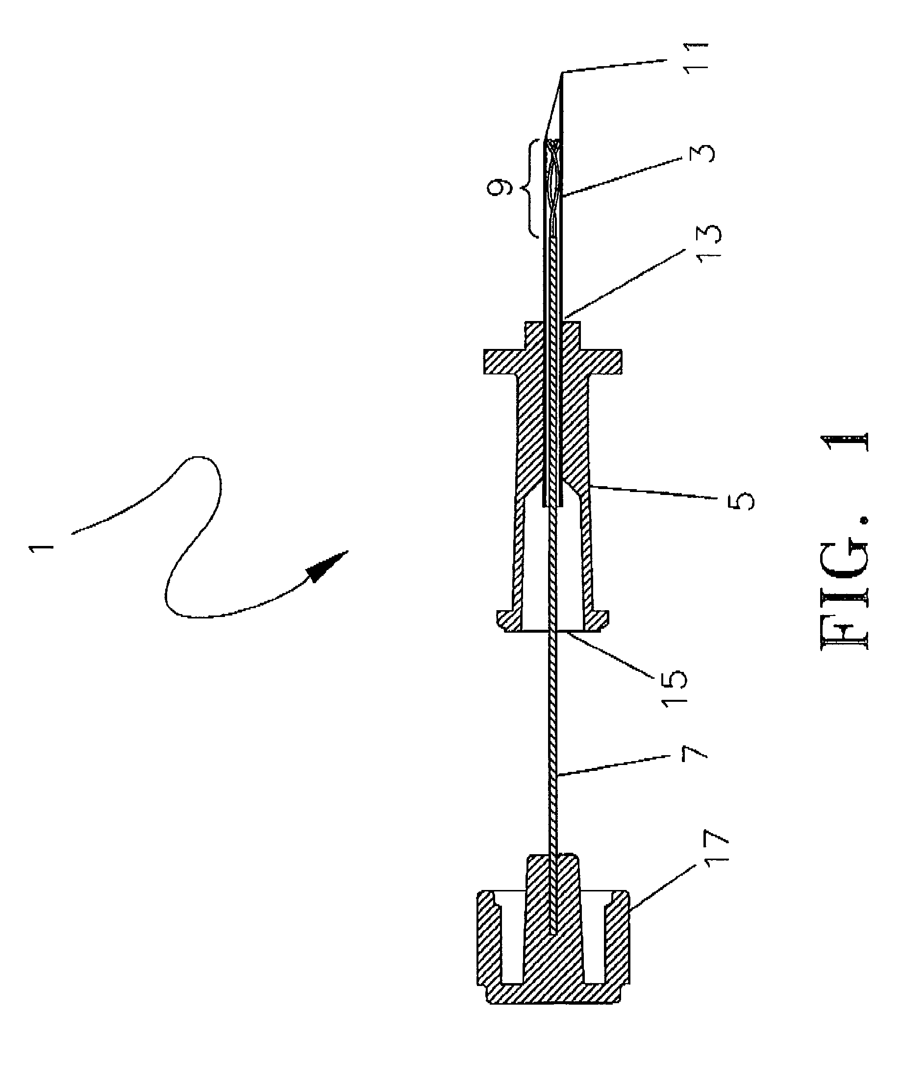
[0035]A preferred embodiment of the targeted phlebectomy device 1 is shown in FIG. 1. The assembly includes a needle 3, a hub 5, a deployment device such as a plunger rod 7 and an engaging element 9. In the embodiment shown, the needle 3 is a medical grade stainless-steel needle cannula with a sharp, beveled tip 11 at the distal portion of the needle 3. The proximal section of needle 3 extends into and is secured to a through lumen at opening 13 of the hub 5. A standard adhesive or other bonding method can be used to securely attach the needle 3 to the through lumen opening 13. The needle 3 typically extends distally beyond the through lumen opening 13 by approximately 2.5 cm, although various needle 3 cannula lengths can be used.

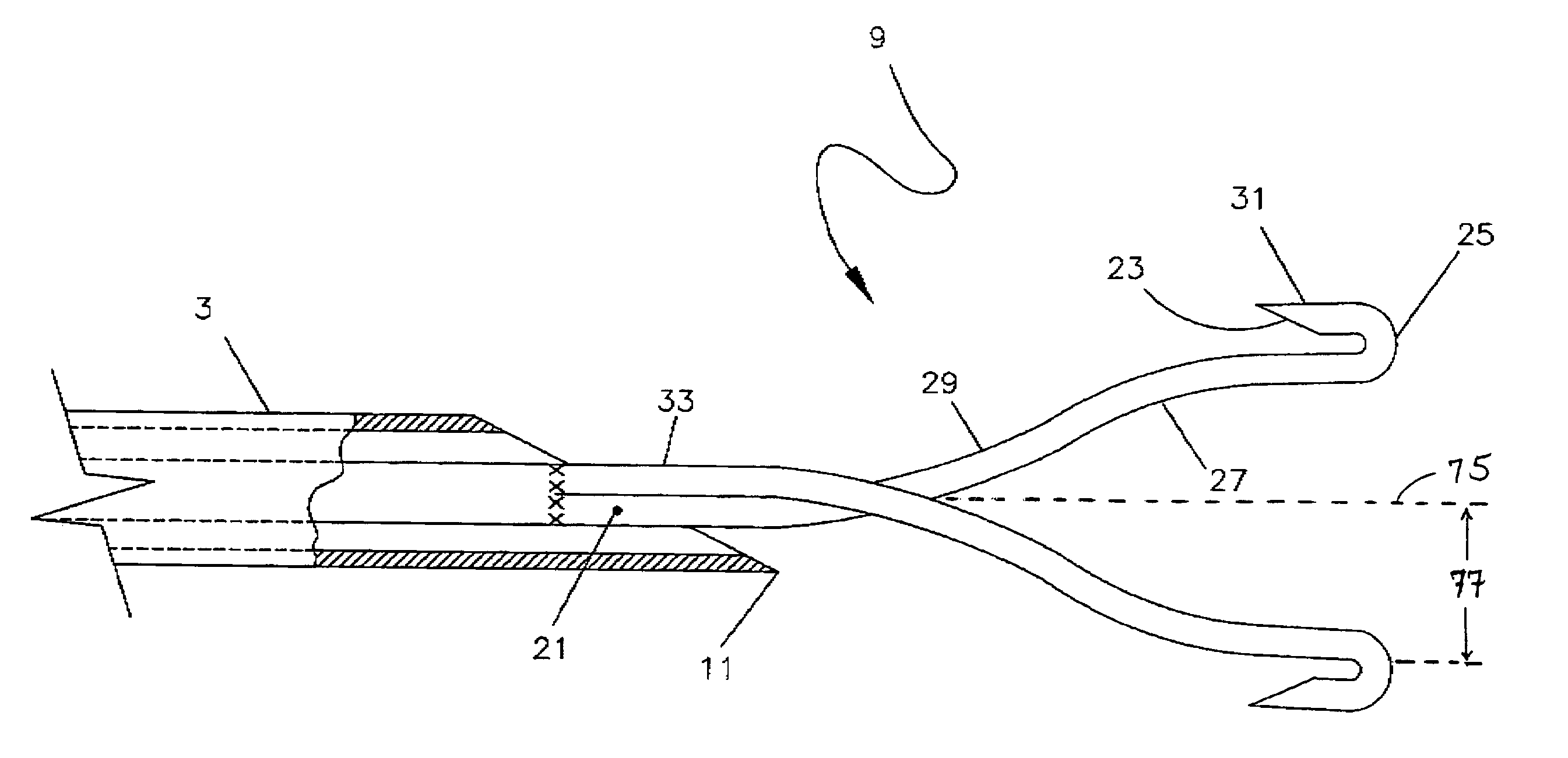
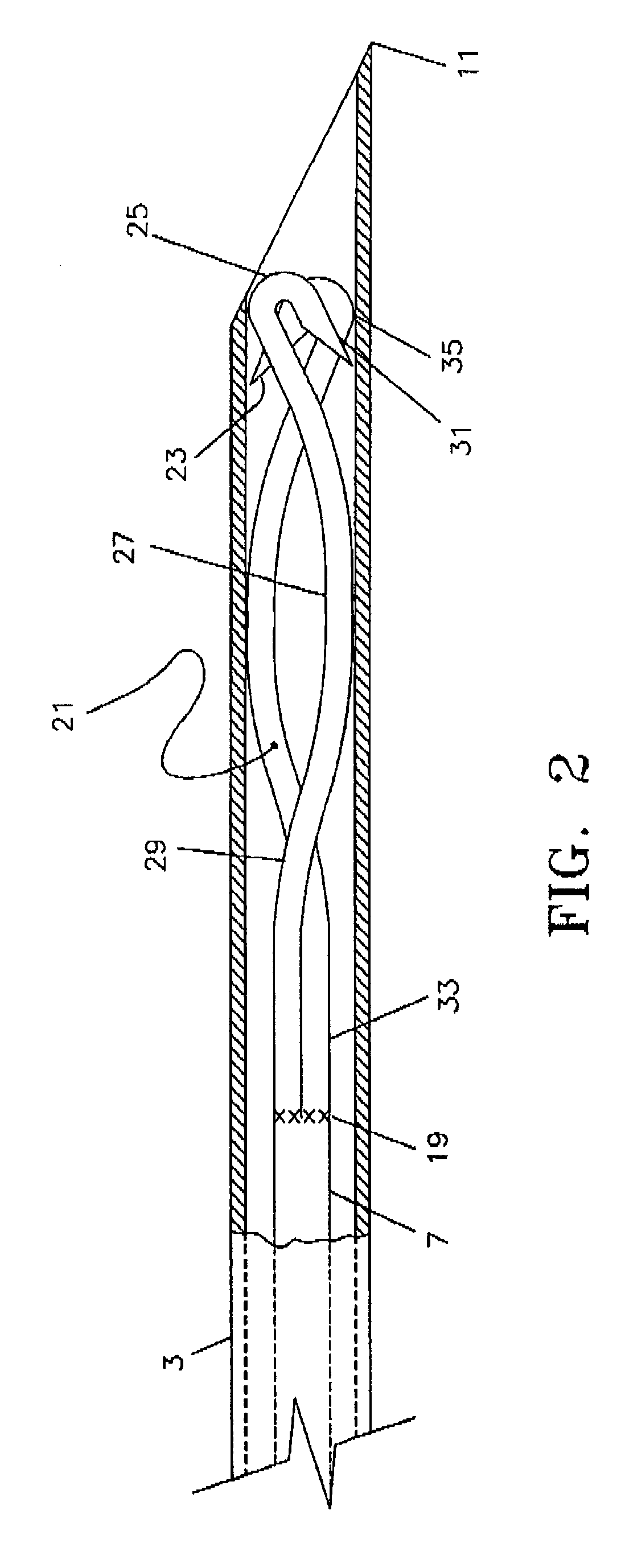
[0036]Housed within the lumen of the needle 3 is the deployable engaging element 9. The engaging element 9 is attached to the distal section of the plunger rod 7 through either a welding or bonding process, as is well known in the art. The weld section of t...


PUM


Abstract

A device for withdrawing a tubular body part such as a varicose vein is provided. A needle is inserted through a skin. The needle contains therein an engaging element in an undeployed state. After the needle is inserted, the engaging element is pushed out of the needle and is typically deployed inside the vein. The vein is now ready to be withdrawn by the deployed engaging element. Using a puncture device that also contains a deployable engaging element allows the puncture site to be small and causes less trauma to the surrounding tissue.

Description

CROSS-REFERENCE TO RELATED APPLICATIONS[0001]This application claims priority to U.S. provisional application No. 60 / 424,528, filed Nov. 6, 2002 and U.S. provisional application No. 60 / 470,077, filed May 13, 2003, both of which are incorporated into the present specification by reference.FIELD OF THE INVENTION[0002]The present invention relates to a medical device for withdrawing a tubular body part, and more particularly, to a device and method for the treatment of varicose veins using ambulatory phlebectomy techniques.BACKGROUND OF THE INVENTION[0003]Varicose veins of the lower extremities is one of the most common medical conditions of the adult population. It is estimated that varicose veins affect approximately 25% of adult females and 10% of males. Symptoms include discomfort, aching of the legs, itching, cosmetic deformities, and swelling. If left untreated, varicose veins may cause medical complications such as bleeding, phlebitis, ulcerations, thrombi and lipodermatoscleros...

Claims


Application Information

Patent Timeline
Patent Type & Authority Patents(United States)
IPC IPC(8): A61B17/00
CPCA61B17/00008A61B2017/00349A61B2017/00778
Inventor SCHUR, ISRAELAPPLING, WILLIAM M.
Owner ANGIODYNAMICS INC
Why Eureka
Try Eureka