
Process and apparatus for converting hydrogen sulfide into hydrogen and sulfur

a technology of hydrogen and sulfur, which is applied in the direction of sulfur preparation/purification, gas-gas reaction process, separation process, etc., can solve the problems of increasing the overall cost of the sulfur recovery process, not desirable, and large quantities of hydrogen sulfide flared

Active Publication Date: 2008-11-25
H2S TECH INC
View PDF17 Cites 17 Cited by
  • Summary
  • Abstract
  • Description
  • Claims
  • Application Information

AI Technical Summary

Benefits of technology

The process achieves efficient production of high-purity hydrogen and sulfur products while reducing the amount of undesirable gases released into the atmosphere, making it more cost-effective and environmentally friendly compared to existing methods.

Problems solved by technology

However, flaring of the hydrogen sulfide converts it to sulfur dioxide which is a major component of acid rain.
Thus, flaring of the hydrogen sulfide, particularly in large quantities, is not desirable.
However, these systems tend to be costly and still tend to result in significant quantities of hydrogen sulfide which are required to be flared.
However, the use of specialized catalysts and further processing steps tends to increase the overall cost of the sulfur recovery process, as well as increase the overall energy requirements of the process.
Further, some sulfur dioxide continues to be produced and released to the atmosphere as a result of the flaring of unconverted hydrogen sulfide.
However, as with the Claus Process, none of these alternative approaches have been found to be fully satisfactory.
However, the dissociation process also produces a number of other impurities or contaminants in the product stream resulting from the sour gas including COS, CS2, SO2, CO, CO2, H2O and sulfur aerosols.
Further, the dissociation may well result in the production of various undesirable impurities or contaminants in the product stream as noted above.

Method used


Image

  • Process and apparatus for converting hydrogen sulfide into hydrogen and sulfur
  • Process and apparatus for converting hydrogen sulfide into hydrogen and sulfur

Examples


Embodiment Construction

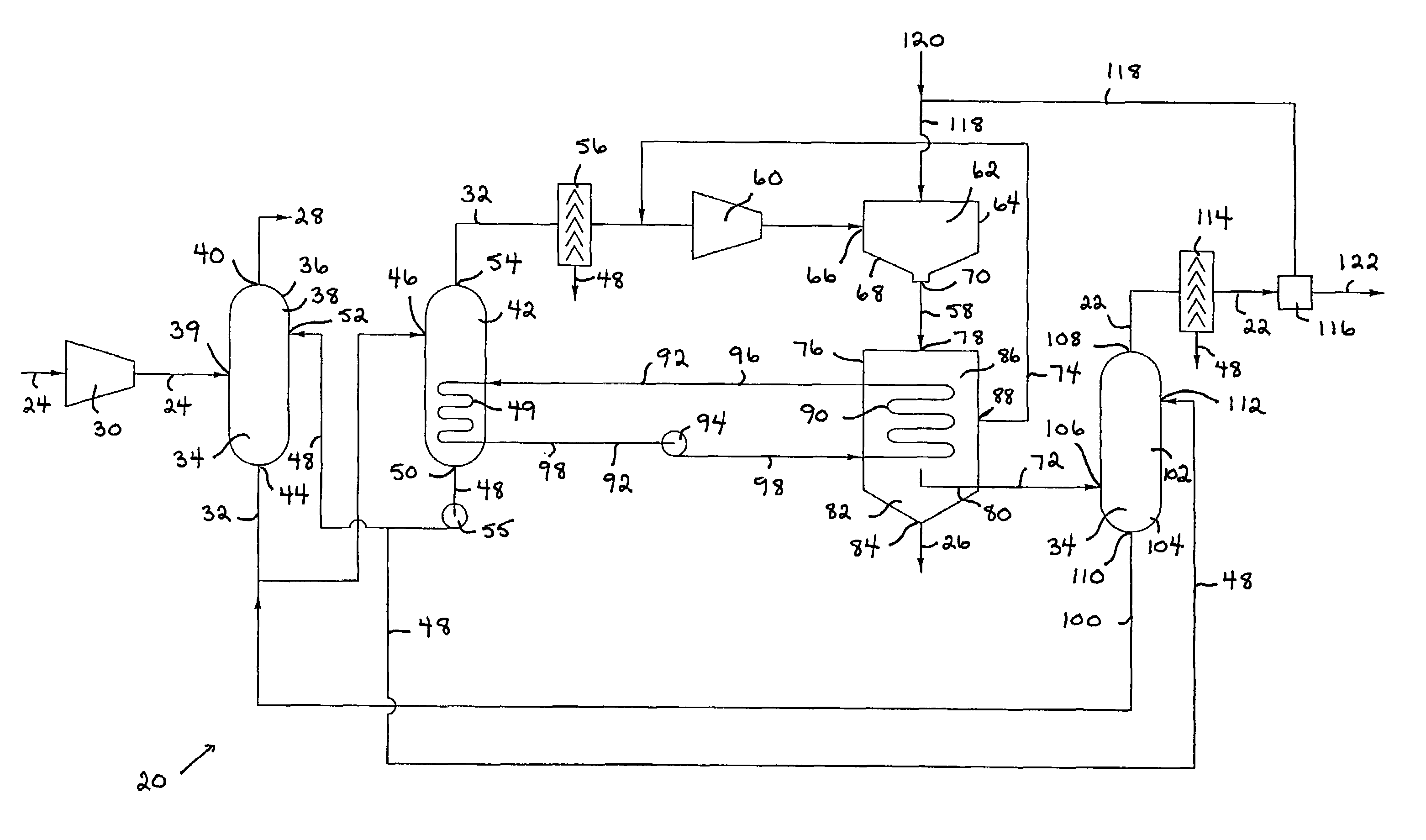
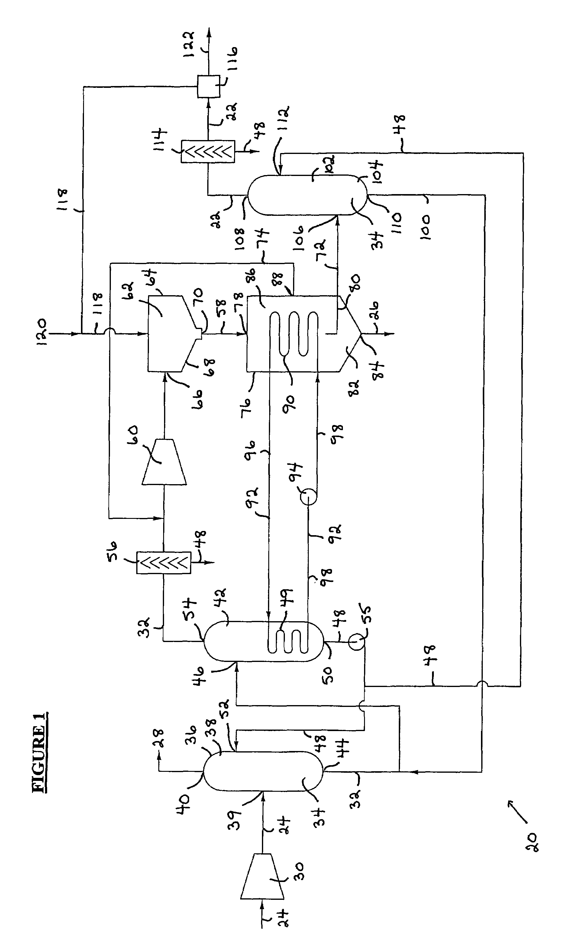
[0091]Referring to FIG. 1, a process and an apparatus (20) are provided for obtaining a hydrogen product (22) from a feed gas (24). The hydrogen product (22) is comprised of elemental hydrogen, while the feed gas (24) is comprised of hydrogen sulfide. Further, the process and the apparatus (20) are also preferably provided for obtaining a sulfur product (26) comprised of elemental sulfur. Finally, any selected impurities or contaminants contained in the feed gas (24), such as carbon dioxide, are separated and produced independently of the hydrogen and sulfur products (22, 26) as a contaminant product (28).

[0092]Thus, in the preferred embodiment, the process and apparatus (20) result in the creation of three product streams. A first product stream is a contaminant or carbon dioxide stream which provides the contaminant product (28). The second product stream is a sulfur stream, particularly a liquid sulfur stream, which provides the sulfur product (26). The third product stream is a ...


PUM

PropertyMeasurementUnit
temperatureaaaaaaaaaa
pressureaaaaaaaaaa

Abstract

A process and apparatus for obtaining a hydrogen product and a sulfur product from a feed gas comprised of hydrogen sulfide. In the process, a first separating step separates the feed gas to obtain a first purified hydrogen sulfide fraction comprised of at least about 90 percent hydrogen sulfide by volume. A dissociating step dissociates hydrogen sulfide present in the first purified hydrogen sulfide fraction to convert it into a dissociated first purified hydrogen sulfide fraction comprised of elemental hydrogen and sulfur. A second separating step separates the dissociated first purified hydrogen sulfide fraction to obtain a hydrogen rich fraction comprised of elemental hydrogen. The sulfur product may also be obtained from the dissociated first purified hydrogen sulfide fraction. Finally, the hydrogen product is obtained from the hydrogen rich fraction. The apparatus is provided for performing the process.

Description

FIELD OF INVENTION[0001]The present invention relates to a process and an apparatus for obtaining a hydrogen product from a feed gas, wherein the feed gas is comprised of hydrogen sulfide and the hydrogen product is comprised of elemental hydrogen. Preferably, the process and the apparatus also obtain a sulfur product comprised of elemental sulfur.BACKGROUND OF INVENTION[0002]Many natural gas formations contain hydrogen sulfide, methane, carbon dioxide and other impurities or contaminants. Typically, these impurities or contaminants must be removed from the natural gas before the natural gas is suitable for use. Similarly, process gases, such as those resulting from gas refining processes or as a by-product of other industrial processes, may contain hydrogen sulfide, methane, carbon dioxide and other impurities or contaminants. These impurities or contaminants must also be removed or otherwise addressed prior to the disposal or further processing and handling of the process gas.[000...

Claims


Application Information

Patent Timeline
Patent Type & Authority Patents(United States)
IPC IPC(8): A62D3/19B01J19/08B01J19/12C01B3/02C01B3/04B01D53/18B01D53/22B01D53/48C01B3/50C01B17/04
CPCC01B3/04C01B17/0495Y10S423/10Y02E60/364Y02E60/36
Inventor SELINGER, RICHARD R.THICKE, BRIAN R.
Owner H2S TECH INC
Learn More