
Membrane-assisted fluid separation apparatus and method

a technology of membrane-assisted fluid separation and membrane, which is applied in the direction of membranes, filtration separation, separation processes, etc., can solve the problems of contaminating the permeate extracted from the hollow interior of the membrane, reducing the efficiency of the entire module, so as to reduce the extensive plumbing apparatus for removing the permeate from the module, the effect of easy disassembly and replacemen

Inactive Publication Date: 2008-12-02
LOEB INVESTORS CO 166 LP +1
View PDF23 Cites 66 Cited by
  • Summary
  • Abstract
  • Description
  • Claims
  • Application Information

AI Technical Summary

Benefits of technology

[0009]The present invention overcomes the above-mentioned problems of the prior art devices. Each bundle of hollow fiber membranes can be assembled prior to its insertion into the housing, no further processing of the bundles is required after being inserted into the housing, the overall fluid separation module design is easy to disassemble and each bundle within the housing can be replaced easily in straightforward manner. These are all desirable features for on-site service of membrane devices. Further, in the present invention, the need for extensive plumbing apparatus to remove the permeate from the module is minimized, which reduces the cost, complexity and maintenance requirements of the invention.

Problems solved by technology

If the resin is not properly applied and leakage of feed occurs from any of the membranes, such leakage results in the contamination of permeate extracted from the hollow interior of the membrane.
Similarly, if leakage-occurs for any other reason, contamination of the fluid permeate results.
Accordingly, one of the disadvantages of having a single module containing hundreds to thousands of membranes is that a defect in just one membrane renders the entire module, with all of the remaining intact membranes, useless.
These prior art devices still present two major problems.
First, if there is a defect in a given membrane within a module that houses a large number of hollow fiber membranes, the entire module containing the defective membrane must be replaced, resulting in the wastage of all other usable membranes in the defective module.
Moreover, in many conventional membrane modules, the housing is made of expensive material or the physical size of said housing is so large that it renders the disposal of the housing for each module along with the membranes contained therein very uneconomical.
Second, whether conventional modules are arranged in series or parallel fashion, extensive plumbing is necessary in order to connect the various modules and to remove the permeate and retentate from each module.
This extensive plumbing adds significantly to the cost of manufacturing and maintaining these prior art devices.
The plumbing also significantly adds to the complexity and bulkiness of these devices.
In general, thermally driven fluid separation processes within conventional membrane-assisted fluid separation modules, especially those processes in which there is a large fraction of liquid feed separated as permeate by evaporation through membranes, are very energy intensive and consuming.
The operation of the process according to prior art is thus very energy intensive and wasteful, as the heat supplied is mainly lost in cooling means (e.g. cooling water etc.).

Method used


Image

  • Membrane-assisted fluid separation apparatus and method
  • Membrane-assisted fluid separation apparatus and method
  • Membrane-assisted fluid separation apparatus and method

Examples


Embodiment Construction

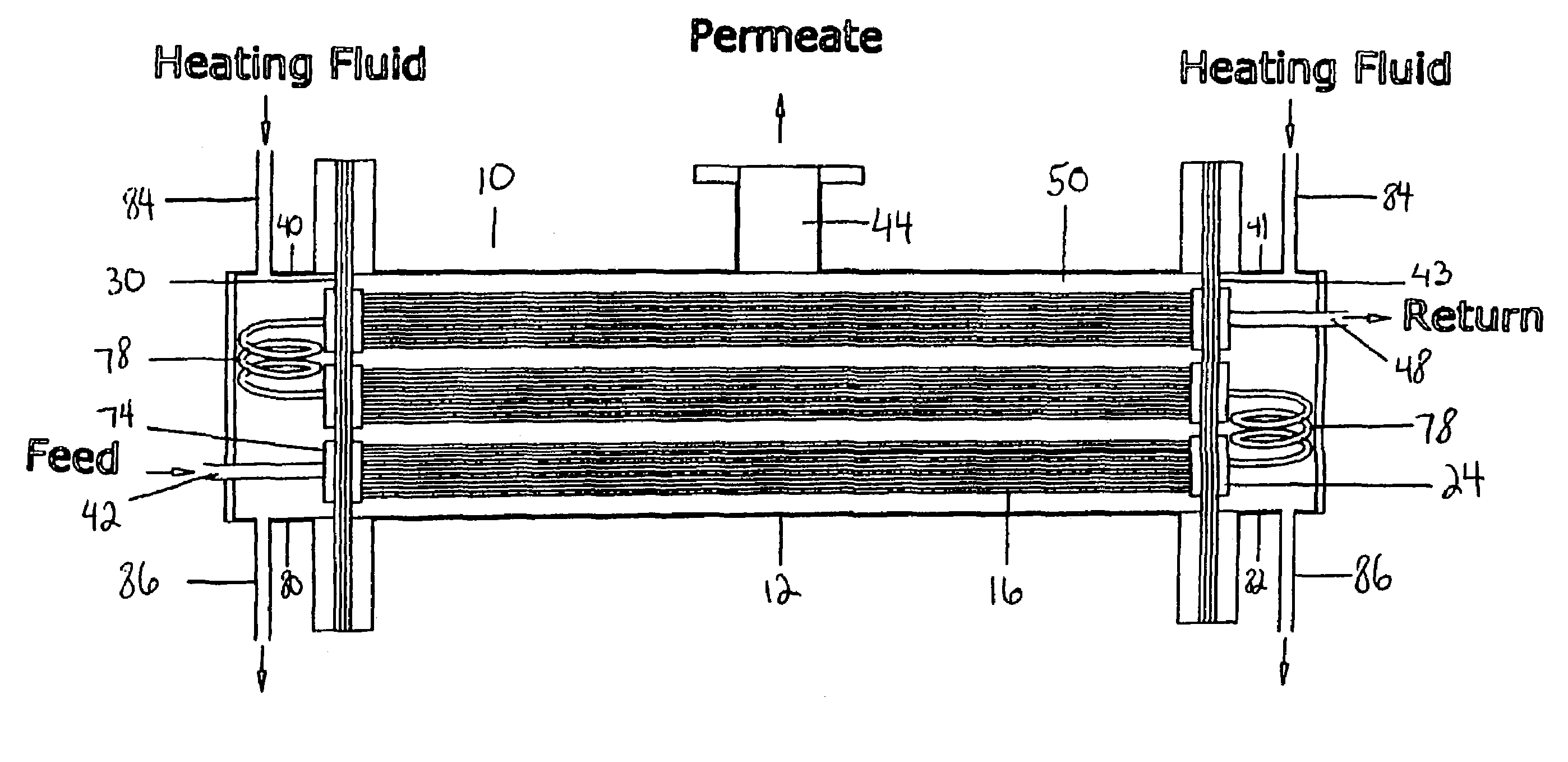
[0049]The present invention provides a fluid separation module used to separate fluid mixtures into permeate and retentate portions by means of membranes adapted for fluid separation. The fluid separation module may be used to perform any membrane-assisted fluid separation processes including but not limited to, pervaporation, vapour permeation, membrane distillation (both vacuum membrane distillation and direct contact membrane distillation), ultra filtration, microfiltration, nanofiltration, reverse osmosis, membrane stripping and gas separation or a combination of any of these processes.

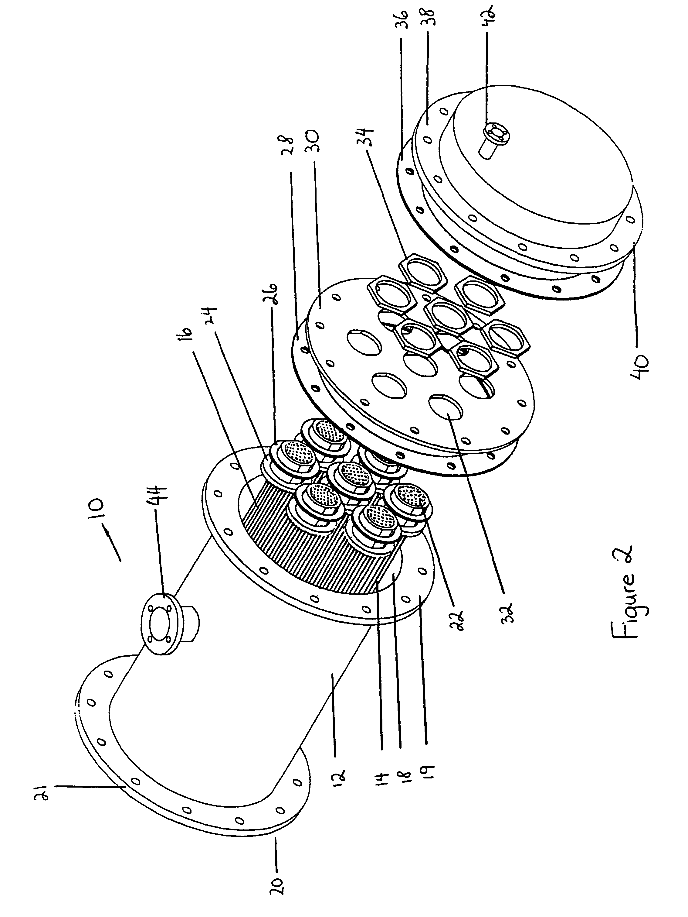
[0050]FIG. 2 illustrates a first preferred embodiment of the fluid separation apparatus 10 of the invention. The apparatus 10 comprises a hollow housing 12 that contains within the lumen of the housing 12, a plurality of elongate hollow fiber membranes 14 which are grouped in at least one bundle 16. Preferably, the housing 12 will contain a plurality of bundles of hollow fiber membranes 16. The bu...


PUM

PropertyMeasurementUnit
lengthaaaaaaaaaa
lengthaaaaaaaaaa
lengthaaaaaaaaaa

Abstract

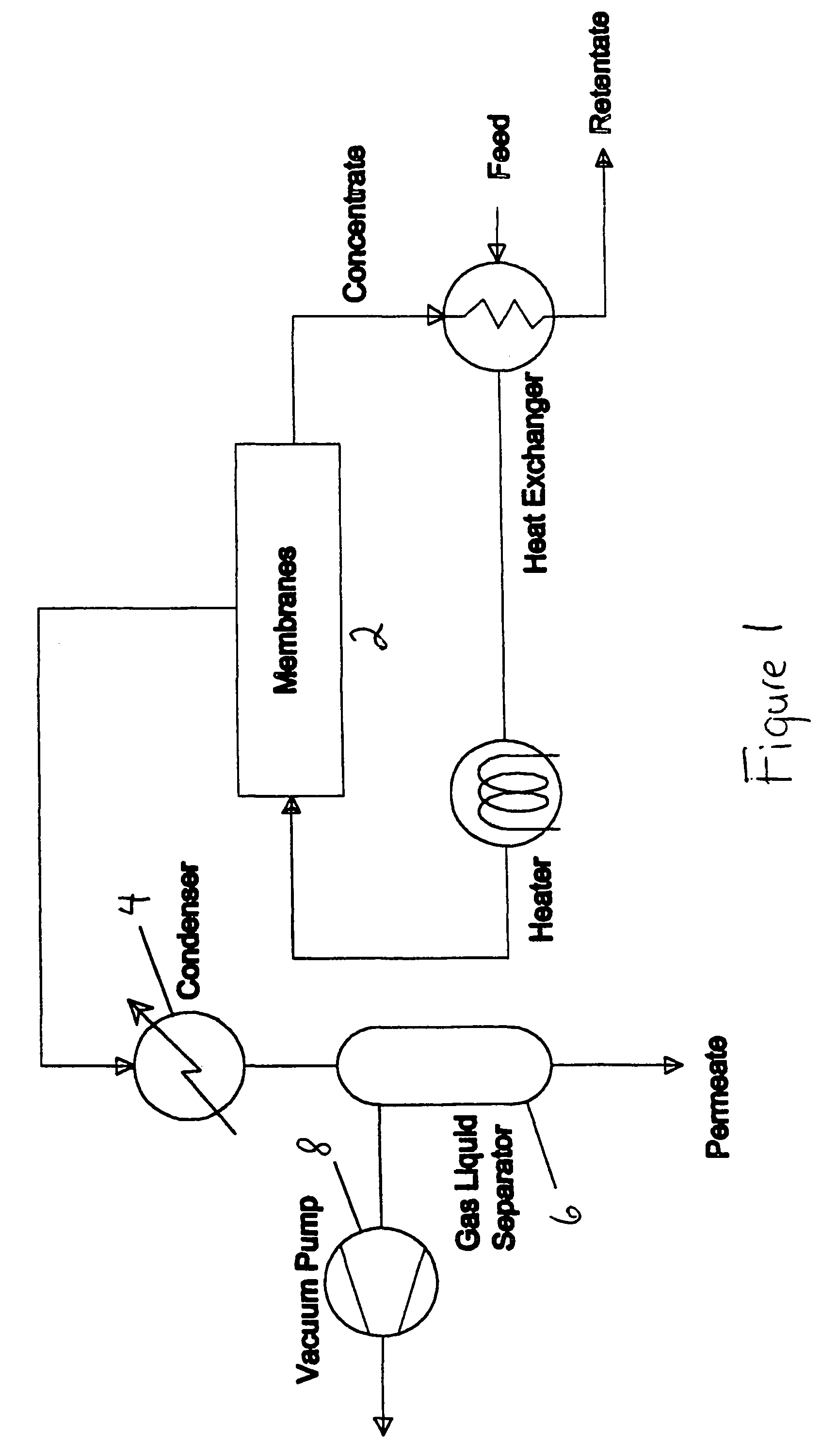
This present invention relates to a fluid separation module adapted to separate a given fluid mixture into permeate and retentate portions using bundles of hollow fiber membranes. The membranes may be composed of different kinds of membranes depending on the application being used to separate the fluid mixture. The fluid separation module may be used to separate fluid mixtures by a number of different processes, including but not limited to, pervaporation, vapour permeation, membrane distillation (both vacuum membrane distillation and direct contact membrane distillation), ultra filtration, microfiltration, nanofiltration, reverse osmosis, membrane stripping and gas separation. The present invention also provides an internal heat recovery process applied in association with those fluid separation applications where separation takes place by evaporation through the membrane of a large portion of the feed into permeate. Desalination and contaminated water purification by means of vacuum membrane distillation are just two examples where the internal heat recovery process may be applied. In these two examples, large portions of the feed are separated by membranes into a high purity water permeate stream by evaporation through the membranes and into a retentate stream containing a higher concentration of dissolved components than present in the feed. In this process the permeate vapour that is extracted from the fluid separation module is compressed by an external compressor to increase the temperature of the vapour higher than the temperature of the feed entering the separation module. Heat from the permeate vapour at the elevated temperature is transferred back to the incoming feed fluid mixture entering the fluid separation module in a condenser / heat exchange.

Description

FIELD OF THE INVENTION[0001]This invention relates to fluid separation. In particular, this invention relates to a fluid separation apparatus comprising of hollow fiber membranes used in fluid processing and a method of fluid separation, including a method of internal heat recovery therein.BACKGROUND OF THE INVENTION[0002]Membrane-assisted fluid separation processes are used to separate fluid mixtures into permeate and retentate portions. These processes may be effected within fluid separation modules that contain a plurality of hollow fiber membranes arranged in an elongated bundle encased in a single shell containment housing. The conventional fluid separation modules using hollow fiber membranes may be configured in either a shell side feed design or a bore side feed design.[0003]Typically, fluid separation modules containing a plurality of hollow fiber membranes arranged in a bundle have potting material, for example epoxy, or other suitable material covering a portion of the ex...

Claims


Application Information

Patent Timeline
Patent Type & Authority Patents(United States)
IPC IPC(8): B01D15/00B01D59/12B01D63/00C02F1/44B01D53/22B01D61/36B01D63/02B01D63/04
CPCB01D53/22B01D61/36B01D63/02B01D63/043C02F1/041C02F1/44B01D2313/20B01D2313/22C02F1/447C02F1/448C02F2103/08Y02A20/131Y02A20/124B01D2313/203B01D63/031B01D2313/221B01D61/3631
Inventor BAIG, FAKHIR U.KAZI, ABDUL M.AL-HASSANI, AISER
Owner LOEB INVESTORS CO 166 LP
Learn More