Compact fluorescent lamp with outer envelope and method for manufacturing

a fluorescent lamp and outer envelope technology, applied in the field of compact fluorescent lamps, can solve the problems of large length dimension, serious difficulties during production, and relatively high price of cfl-s, and achieve the effect of improving the conditions of mass production, facilitating production, and facilitating production

Inactive Publication Date: 2008-12-02
GENERAL ELECTRIC CO
View PDF13 Cites 27 Cited by
  • Summary
  • Abstract
  • Description
  • Claims
  • Application Information

AI Technical Summary

Benefits of technology

[0009]The disclosed compact fluorescent lamp provides for a firm and vibration damping mechanical fixing of the CFL components as well as a simplified method of production thereof. By using a holding and protecting shield according to the invention, the ballast circuit and the discharge tube arrangement are held within the outer envelope and relative to each other in a predetermined position. A further advantage accomplished by the invention is an effective protection of the ballast circuit against heat applied during connecting of the two separated parts of the outer envelope. Most of the consecutive manufacturing steps used during the production of a conventional incandescent lamp may be maintained, thereby providing better conditions for mass production. The use of a flare with an exhaust tube provides a possibility to make benefit of the production line used for manufacturing conventional incandescent lamps, which also reduces the cost of production especially when compared with other GLS (General Lighting Service) look alike lamps. Further advantage of this lamp is the full mechanical and electric compatibility with bulb-shaped incandescent lamps that makes it an efficient replacement lamp. The proposed lamps provide a certain level of protection against environmental load due to the outer envelope.

Problems solved by technology

Disadvantageous is however in CFL-s their relatively high price and large length dimension.
Although this lamp is provided with integrated ballast inside the outer envelope, serious difficulties may arise during production due to the use of the heat shield disposed between the lamp and the ballast.

Method used


Image

  • Compact fluorescent lamp with outer envelope and method for manufacturing
  • Compact fluorescent lamp with outer envelope and method for manufacturing
  • Compact fluorescent lamp with outer envelope and method for manufacturing

Examples


Embodiment Construction

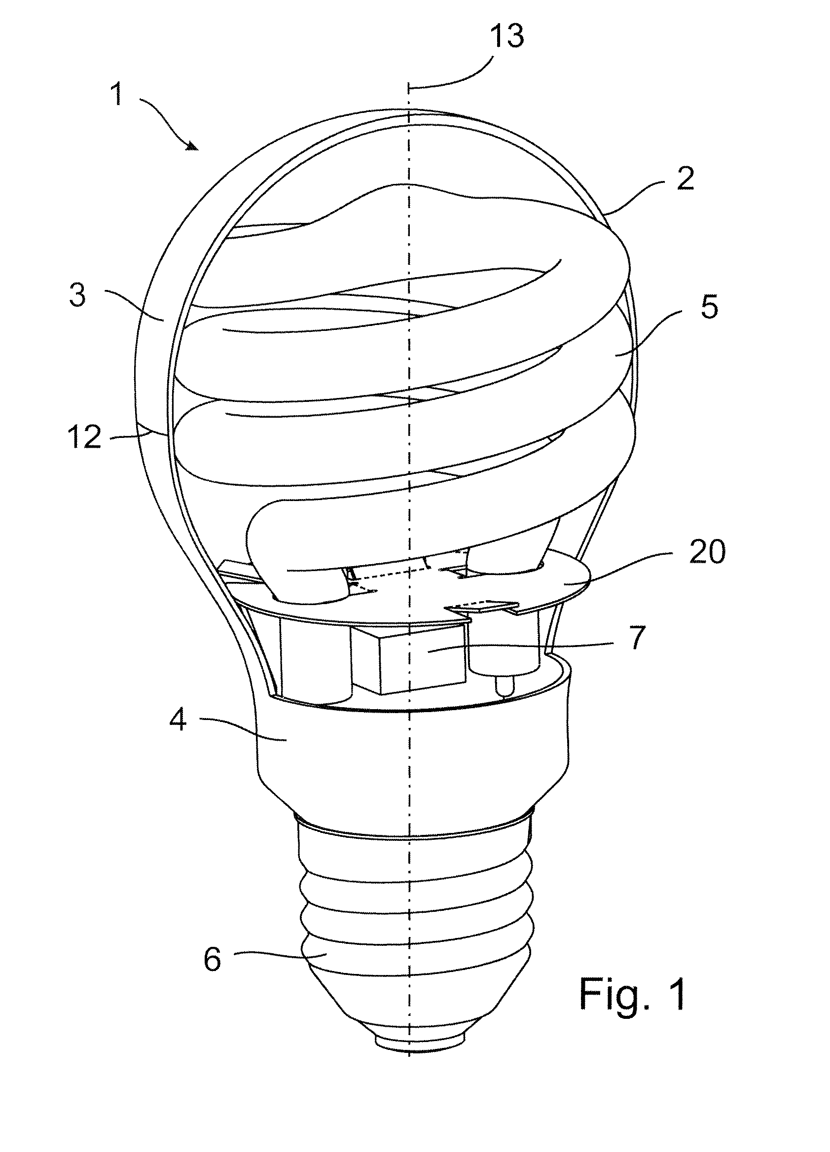
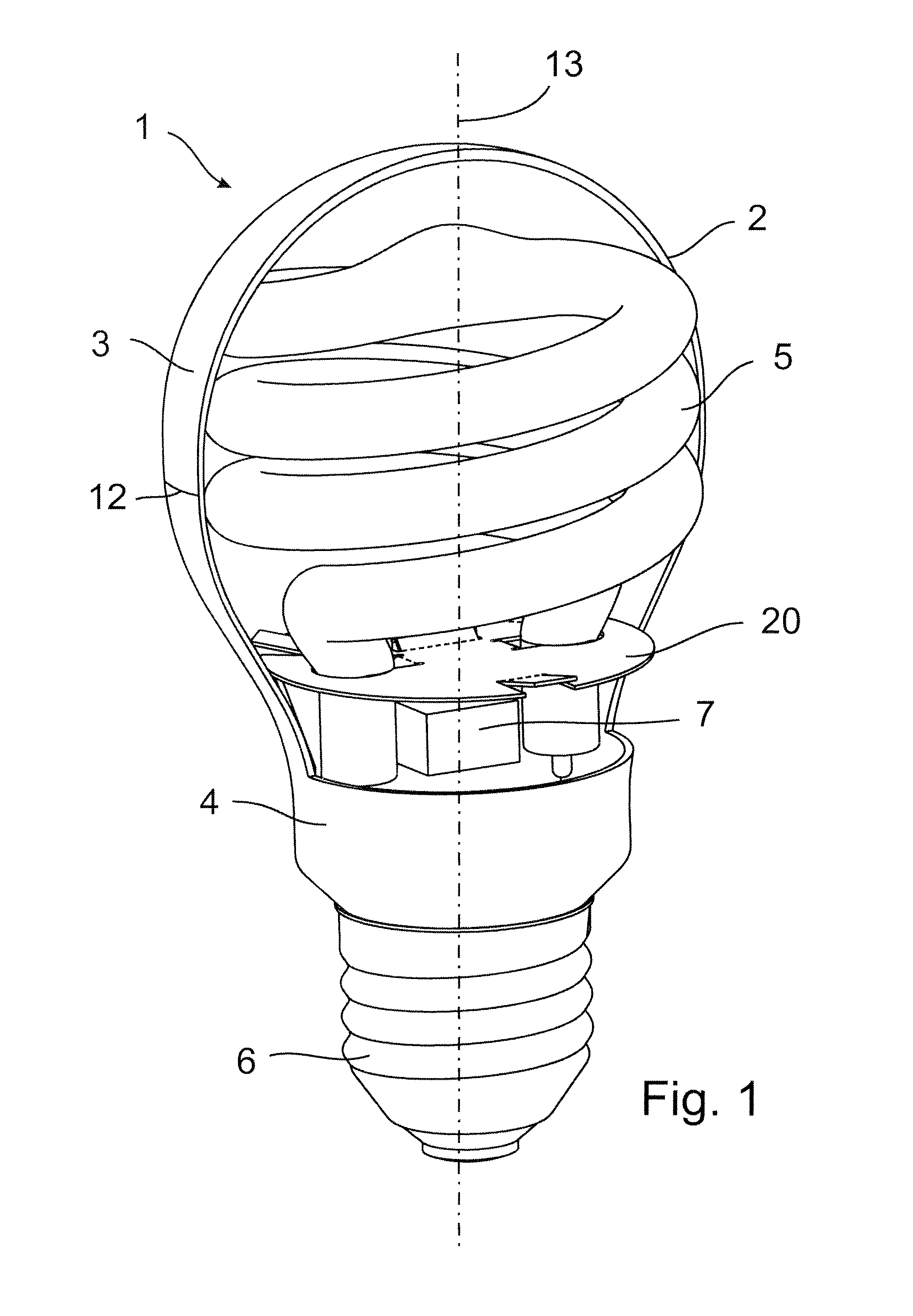
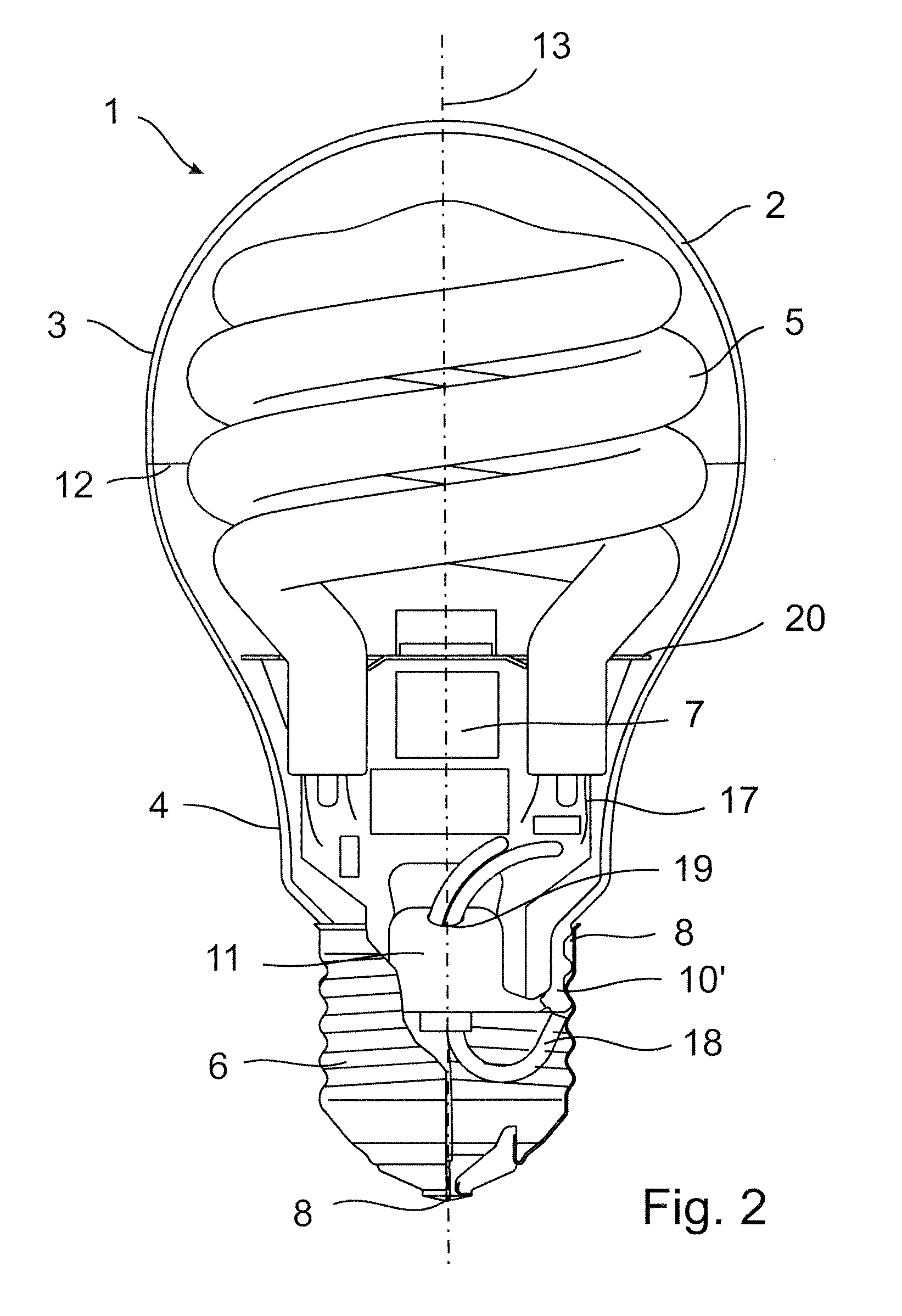
[0023]Referring first to FIGS. 1 to 3, a low-pressure discharge lamp 1 is shown. The lamp is a fluorescent discharge lamp, with an outer envelope 2 enclosing a discharge tube arrangement 5 and a ballast circuit 7. The outer envelope 2 has a spherical part 3 and a longitudinal part 4 with an open-ended neck portion 10 connected to a base 6 and defines a principal axis 13. FIG. 2 shows a threaded neck portion 10′ for connection to a screw type base and FIG. 3 shows a neck portion 10 for connection to a bayonet base. The outer envelope is cut in two parts and separated at a cutting line 12 in order that the ballast circuit 7 and the discharge tube arrangement 5 can be inserted and connected inside the outer envelope 2 as described in detail below. The discharge tube arrangement 5 may comprise a single discharge tube or a plurality of elongated discharge tubes. The discharge tubes are made of glass, enclose a discharge volume filled with a discharge gas, and have a fluorescent phosphor ...


PUM


Abstract

A compact fluorescent lamp comprises a discharge tube arrangement with at least one discharge tube. The tube is formed of glass, encloses a discharge volume filled with a discharge gas and has a fluorescent phosphor coating disposed on the inner surface of the tube. The tube forms a continuous arc path and is provided with electrodes disposed at each end of the arc path. The lamp also comprises a ballast circuit mounted on a printed circuit board, which is oriented in a plane substantially parallel to the principal axis of the lamp. The ballast circuit is connected to the electrodes by lead-in wires and to a supply voltage by lead-out wires and controls the current in the tube. A bulb shaped outer envelope has a substantially spherical portion enclosing at least a part of the tube arrangement and an elongated end portion enclosing at least the ballast circuit. The end portion of the outer envelope having an open end on a base side is closed and terminated by a closing means of a material compatible with the material of the outer envelope. The ballast circuit and the discharge tube arrangement are held within the outer envelope and relative to each other in a predetermined position by a holding and protecting shield being oriented in a plane substantially perpendicular to the principal axis of the lamp and comprising a receiving and fixing portion for the discharge tube and the printed circuit board of the ballast circuit.A method for manufacturing a compact fluorescent lamp as described above is also disclosed. In the proposed method, the ballast circuit and the discharge tube arrangement are inserted into and attached to a holding and protecting shield.

Description

FIELD OF THE INVENTION[0001]This invention relates to compact fluorescent lamps (CFL), and more particularly to compact fluorescent lamps that can replace incandescent lamps of general purpose. Even more specifically the invention relates to low-pressure compact fluorescent lamps that have an outer envelope and a ballast circuit within the outer envelope.BACKGROUND OF THE INVENTION[0002]The majority of the known and commercially available low-pressure discharge lamps are so-called compact fluorescent lamps at present. These lamps are determined to replace incandescent lamps used in a wide field of industry and home applications. Main advantages of these lamps are low power consumption and a long lifetime. Disadvantageous is however in CFL-s their relatively high price and large length dimension. Many configurations have been proposed to solve the length dimension problem. Such solutions include the multiple tube arrangements and the coiled tube arrangements.[0003]U.S. Pat. No. 4,527...

Claims


Application Information

Patent Timeline
Patent Type & Authority Patents(United States)
IPC IPC(8): H01J7/44
CPCH01J9/247H01J61/327H01J61/34H01J61/56Y02B20/19Y02B20/00
Inventor WURSCHING, ISTVANFULOP, JOZSEFPAPP, FERENCBANKUTI, LASZLO
Owner GENERAL ELECTRIC CO
Why Eureka
Try Eureka