Method and system for dissipating thermal energy from conduction-cooled circuit card assemblies which employ remote heat sinks and heat pipe technology

a technology of conduction-cooled circuit card and thermal energy, which is applied in the direction of domestic cooling devices, electrical apparatus casings/cabinets/drawers, instruments, etc., can solve the problems of insufficient performance of conventional thermal conduction systems, and increased heat generation at the modules

Inactive Publication Date: 2008-12-02
TRACEWELL SYST
View PDF26 Cites 68 Cited by
  • Summary
  • Abstract
  • Description
  • Claims
  • Application Information

AI Technical Summary

Benefits of technology

[0007]The method at hand permits a substantial design flexibility in developing system architectures. For instance, in one embodiment, the chassis is configured with oppositely disposed sides extending between end portions and including a bottom region and a top region. The backplane for this arrangement is supported at the bottom region and one or more of the remote heat sink assemblies are mounted within the chassis generally below that backplane. With this structuring, the chassis may define an air flow path extending between the top region across the one or more proximate heat sink assemblies and across the one or more remote heat sink assemblies as well as the chassis fin portion. Where the pitch or spacing between circuit card assemblies is adequate, the heat pipes may be embedded within the conduction rail structure and bent to remain internal and extend to the remote one or more heat sinks. A particular advantage of the system is a lessoning of the number of air flow driving fans. For example, two such fans may be adequate with a third permitting operation of the system at altitudes of 10,000 feet.
[0010]Where a desired chassis architecture is, for instance, under severe widthwise constraint, the proximate heat sink assemblies may be eliminated while the length of the chassis may be expanded through the utilization of one or more remote heat sinks extending from the rear portion of the chassis.

Problems solved by technology

While the earlier conduction-based systems functioned adequately in carrying out heat dissipation, as electronic systems including power supplies have become more complex and functionally elaborate, heat generation at the modules has been seen to substantially increase and the conventional thermal conduction systems have been unable to perform adequately.
However, such facilities may be vulnerable to harsh environments, or may not be available or acceptable for a variety of reasons.
The inadequacies of the conventional approaches also have imposed limitations on the capability of retrofitting 20 or 25 year old platforms, for example, located in aircraft, with modern electronic systems.
For a similar architecture but with a shorter pitch or card-to-card spacing there is insufficient room for embedding heat pipes within the internal conductive rail structure.

Method used


Image

  • Method and system for dissipating thermal energy from conduction-cooled circuit card assemblies which employ remote heat sinks and heat pipe technology
  • Method and system for dissipating thermal energy from conduction-cooled circuit card assemblies which employ remote heat sinks and heat pipe technology
  • Method and system for dissipating thermal energy from conduction-cooled circuit card assemblies which employ remote heat sinks and heat pipe technology

Examples


Embodiment Construction

[0039]In the discourse to follow a conduction-cooled circuit card assembly (CCA) as described, for instance, in the above referenced IEEE Standard is disclosed, whereupon the approach by which the method and system set forth herein evolved is discussed. The description then turns to a discussion of heat pipe technology whereupon a chassis carrying 21 CCAs and the conduction-cooling approach of the disclosure is described. Other chassis architectures then are described.

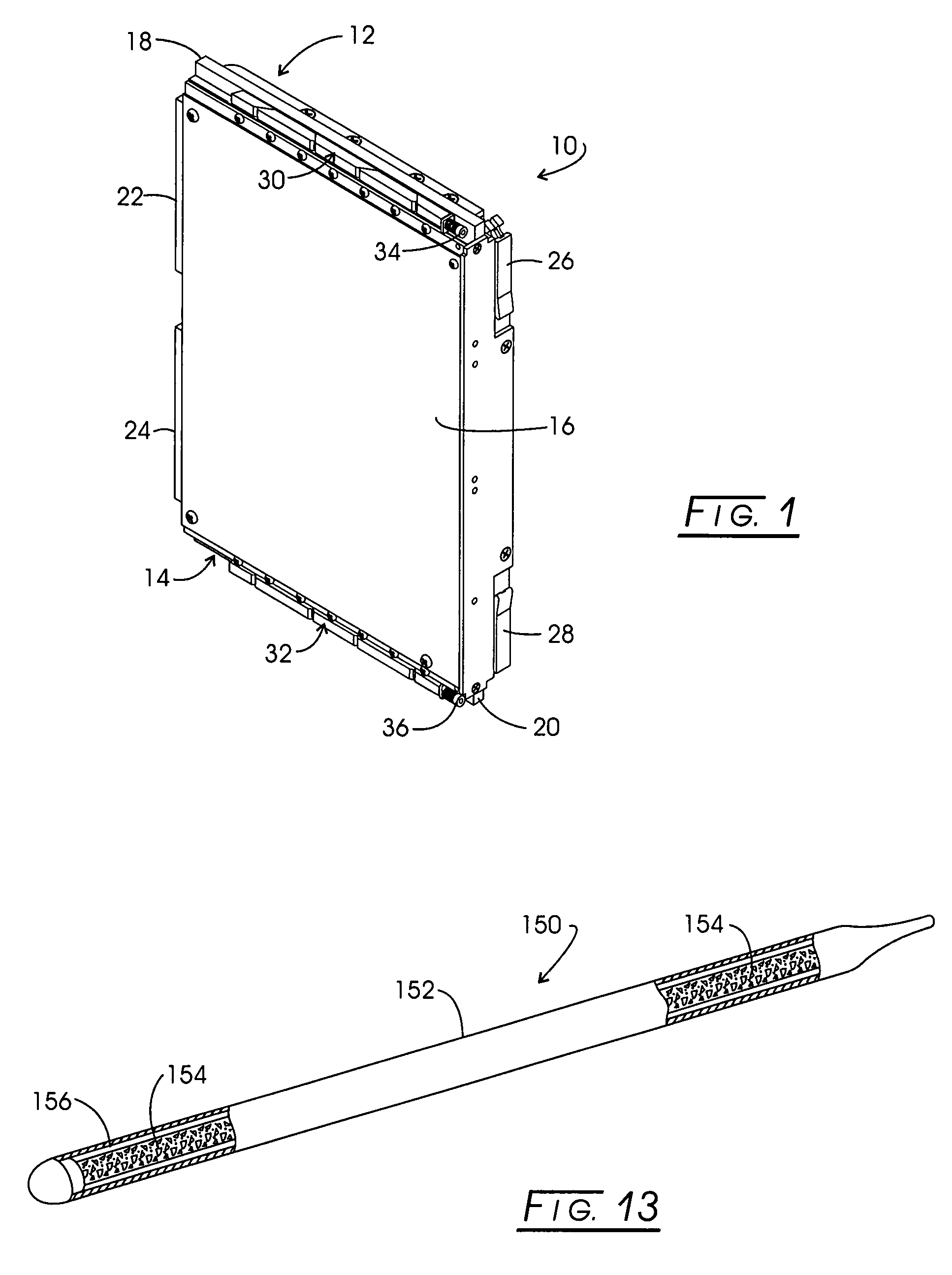
[0040]Looking to FIG. 1, a conduction-cooled Eurocard (CCA) is represented generally at 10. CCA 10 is configured with a double-height or 6 U, nominal×160 mm format functioning to carry heat from a component carrying printed wiring board (PWB) to oppositely disposed edge regions represented generally at 12 and 14. Device 10 is formed with a metal plane with a conductive heat management layer or component 16. Management layer 16 performs in conjunction with optional stiffening ribs and heat transferring connectors 18 and...


PUM


Abstract

Method and System for dissipating thermal energy from conduction-cooled circuit card assemblies in which thermal energy is directed into proximate heat sink assemblies and additionally is conveyed by heat pipes to one or more remote heat sink assemblies configured for the transfer of thermal energy to a flow of air and located within a chassis at a position remote from the system thermal load.

Description

CROSS-REFERENCE TO RELATED APPLICATIONSSTATEMENT REGARDING FEDERALLY SPONSORED RESEARCH[0001]Not applicable.BACKGROUND OF THE INVENTION[0002]Industry and governmental entities have developed requirements for operating sophisticated electronics within harsh environments with extreme temperature, shock and vibration. For performing under these conditions, systems typically involve robust and sometimes sealed chassis assemblies which are called upon to perform with conduction-cooled circuit card assemblies (CCAs) or modules. These modules themselves are environmentally protected by enclosure within shell-like structures incorporating conduction frames or a three-dimensional conduction plate which conduct an electronically evolved heat energy to oppositely disposed sides or edge regions. When positioned within a chassis, the module engages a backplane as well as the oppositely disposed card slots or channels of robust thermally conductive conduction rails. The sides or edge regions of t...

Claims


Application Information

Patent Timeline
Patent Type & Authority Patents(United States)
IPC IPC(8): H05K7/20H01L23/36
CPCH05K7/20672
Inventor TRACEWELL, MATTHEW S.CHEN, GARY G.
Owner TRACEWELL SYST
Why Eureka
Try Eureka