Oxygen sensor heater control methods and systems

a technology of oxygen sensor and heater, which is applied in the direction of electric control, fuel injection control, machines/engines, etc., can solve the problems of ceramic element cracking, oxygen sensor element cracking,

Inactive Publication Date: 2008-12-23
GM GLOBAL TECH OPERATIONS LLC
View PDF13 Cites 14 Cited by
  • Summary
  • Abstract
  • Description
  • Claims
  • Application Information

AI Technical Summary

Problems solved by technology

Cracking of oxygen sensor elements may occur due to thermal shock.
If the element has, by this point in time, reached a hot enough temperature, the water droplet can cause the ceramic element to crack.

Method used


Image

  • Oxygen sensor heater control methods and systems
  • Oxygen sensor heater control methods and systems
  • Oxygen sensor heater control methods and systems

Examples


Embodiment Construction

[0016]The following description is merely exemplary in nature and is not intended to limit the present disclosure, application, or uses. It should be understood that throughout the drawings, corresponding reference numerals indicate like or corresponding parts and features. As used herein, the term module refers to an application specific integrated circuit (ASIC), an electronic circuit, a processor (shared, dedicated, or group) and memory that executes one or more software or firmware programs, a combinational logic circuit, and / or other suitable components that provide the described functionality.

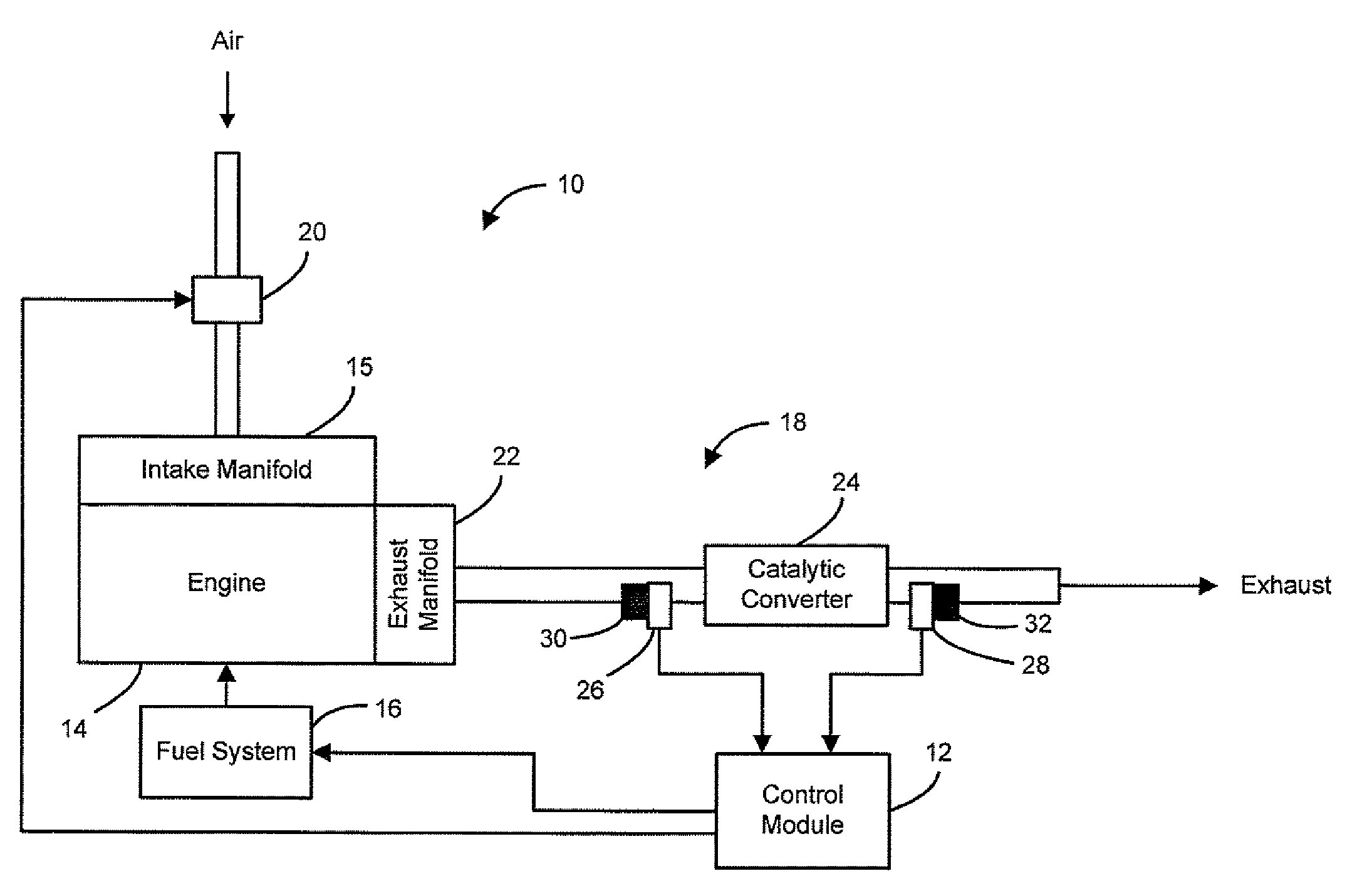
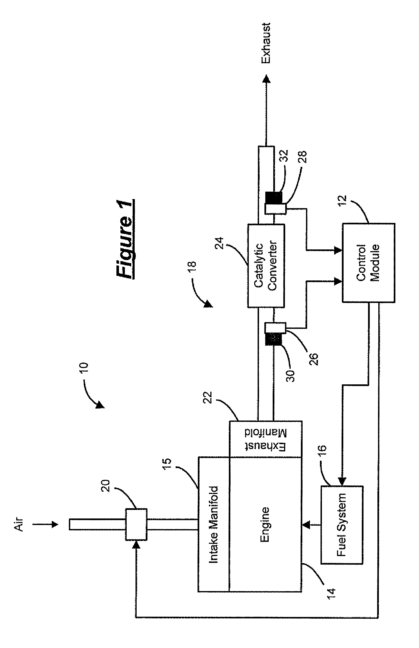
[0017]Referring now to FIG. 1, a vehicle 10 includes a control module 12, an engine 14, a fuel system 16, and an exhaust system 18. A throttle 20 communicates with the control module 12 to control air flow into an intake manifold 15 of the engine 14. The amount of torque produced by the engine 14 is proportional to mass air flow (MAF) into the engine 14. The engine 14 operates in a lean c...


PUM


Abstract

A control system for an oxygen sensor heater is provided. The control system includes a passive heater control module that generates a heater control signal at a first duty cycle and measures a resistance of the oxygen sensor heater. An exhaust gas temperature mapping module maps the resistance to an exhaust gas temperature. An active heater control module generates a heater control signal at a second duty cycle based on the exhaust gas temperature.

Description

FIELD[0001]The present disclosure relates to methods and systems for controlling an oxygen sensor heater.BACKGROUND[0002]The statements in this section merely provide background information related to the present disclosure and may not constitute prior art.[0003]Engine control systems manage air and fuel delivery to the engine based on either open loop or closed loop feedback control methods. Open loop control methods are typically initiated during specific operating conditions such as start up, cold engine operation, heavy load conditions, wide open throttle, and intrusive diagnostic events, etc. An engine control system typically employs closed loop control methods to maintain the air / fuel mixture at or close to an ideal stoichiometric air / fuel ratio. Closed loop fuel control commands a desired fuel delivery based on an oxygen content in the exhaust. The oxygen content in the exhaust is determined by oxygen sensors that are located downstream of the engine.[0004]Oxygen sensors gen...

Claims


Application Information

Patent Timeline
Patent Type & Authority Patents(United States)
IPC IPC(8): F02D41/00F02D41/02
CPCF02D41/1494F02D41/1446F02D2041/2027
Inventor ADAMS, JUSTIN F.AVALLONE, LOUIS A.MCKIM, DALE W.SELL, JEFFREY A.SIEKKINEN, JOHN W.VERDEJO, JULIAN R.
Owner GM GLOBAL TECH OPERATIONS LLC
Why Eureka
Try Eureka