Overcurrent detection circuit and power supply apparatus provided therewith

a detection circuit and power supply technology, applied in the direction of pulse technique, process and machine control, instruments, etc., can solve the problems of failure to start, start-up failure, start-up failure, etc., to enhance the reliability reduce the mounting area of the power supply apparatus, and ensure the effect of overcurrent protection

Active Publication Date: 2008-12-23
ROHM CO LTD
View PDF10 Cites 17 Cited by
  • Summary
  • Abstract
  • Description
  • Claims
  • Application Information

AI Technical Summary

Benefits of technology

[0031]As described above, according to the overcurrent detection circuit of the present invention, it is possible to achieve optimum overcurrent protection depending on the state of a power supply apparatus or the like. This makes it possible to enhance the reliability of the power supply apparatus or the like, and achieve reduction in the mounting area thereof as well as in the cost thereof.

Problems solved by technology

However, the first method described above has the disadvantage that, if the overcurrent protection function operates as a result of a relatively high current (an inrush current) passing through the power supply apparatus 100 at start-up, the output voltage VL becomes 0 V, and therefore the power supply apparatus 100 fails to start (start-up failure occurs).
Such start-up failure occurs notably in a case where the load 102 has a large input capacitance.
This unfavorably leads to damage (damage by heat) not only of the MOS transistor 101 but also of the diode 105, the inductor 106, and the load 102, for example, and thus reduces the reliability of the power supply apparatus 100.
This leads to a larger mounting area, and also to a higher cost.

Method used


Image

  • Overcurrent detection circuit and power supply apparatus provided therewith
  • Overcurrent detection circuit and power supply apparatus provided therewith
  • Overcurrent detection circuit and power supply apparatus provided therewith

Examples


first embodiment

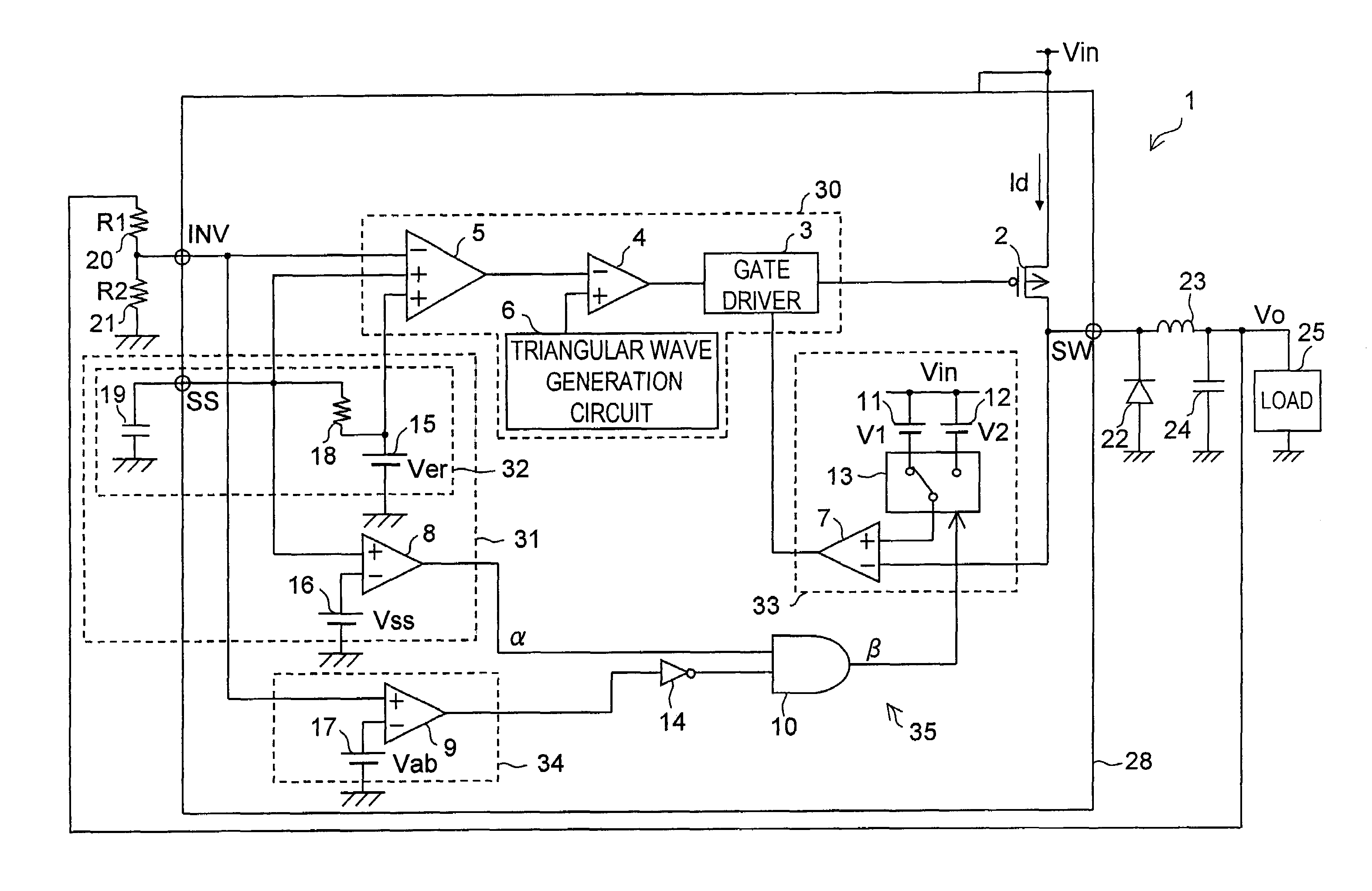
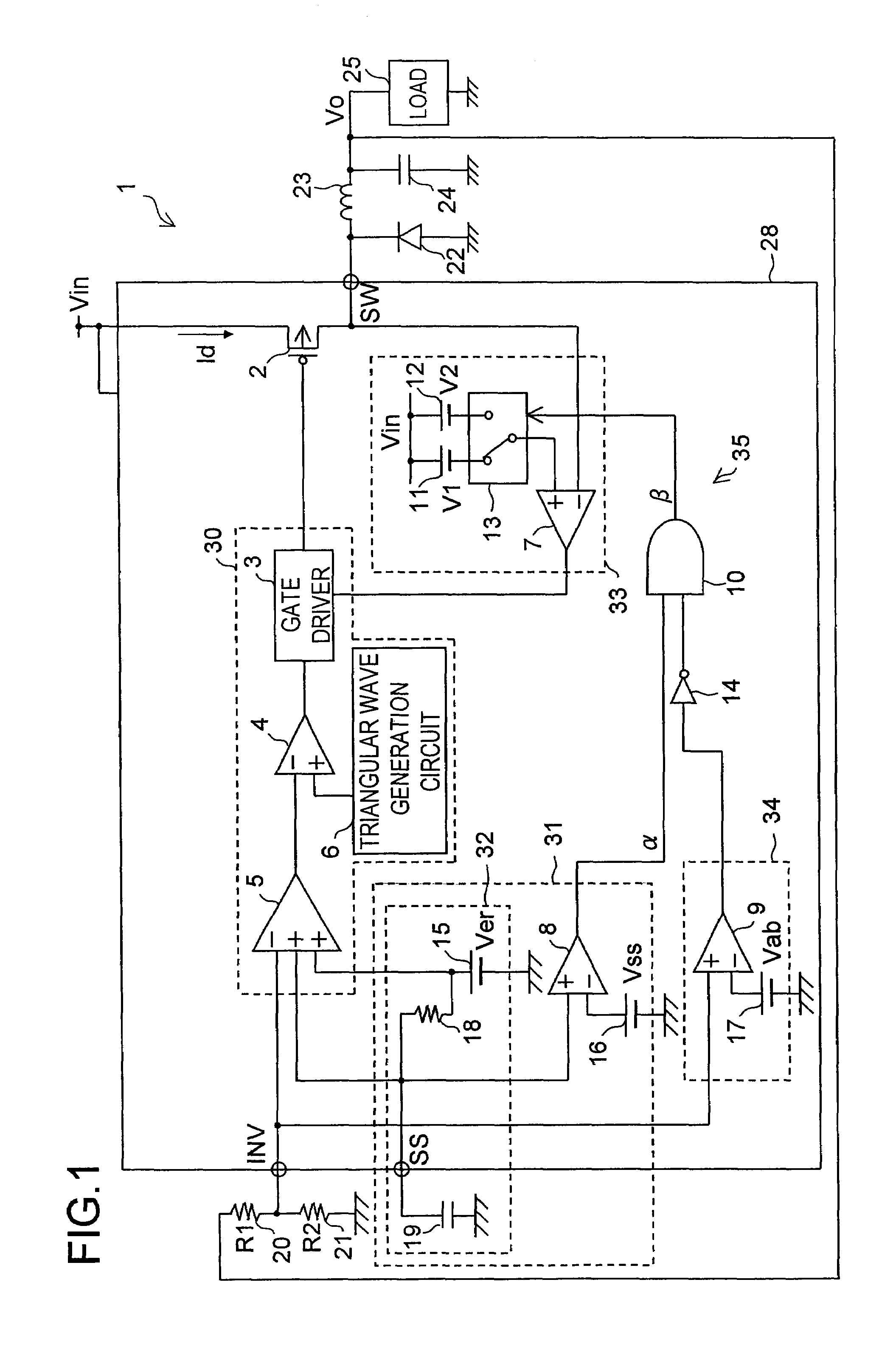
[0063]Hereinafter, a first embodiment of the overcurrent detection circuit of the present invention and the power supply apparatus provided with such an overcurrent detection circuit will be described. FIG. 1 is a diagram showing the circuit configuration of a power supply apparatus 1 of the first embodiment.

[0064](FIG. 1: Description of the Configuration)

[0065]The source electrode of a P-channel MOS transistor 2 serving as a switching element is fed with an input voltage Vin fed from the outside, and the drain electrode thereof is connected to the inverting input terminal (−) of a comparator 7, to the cathode of a diode 22, and to one end of an inductor 23. The other end of the inductor 23 is grounded via a circuit in which a capacitor 24 for smoothing an output voltage Vo to be applied to a load 25 and the load 25 are connected in parallel. The anode of the diode 22 is grounded. As described above, the drain electrode of the MOS transistor 2 is made to output a current (feed elect...

second embodiment

[0115]Next, a second embodiment of the overcurrent detection circuit of the present invention and the power supply apparatus provided with such an overcurrent detection circuit will be described. FIG. 3 is a diagram showing the circuit configuration of a power supply apparatus 51 of the second embodiment. In FIG. 3, such components as are found also in FIG. 1 will be identified with common reference characters and their detailed descriptions will be omitted.

[0116]The power supply apparatus 51 differs from a power supply apparatus 1 in the following respects. The power supply apparatus 51 is provided with, instead of an integrated circuit element 28, an integrated circuit element 58, which does not have a switching element corresponding to a MOS transistor 2. As a switching element corresponding to the MOS transistor 2, a P-channel MOS transistor 52 is provided outside the integrated circuit element 58. The output of a gate driver 3 is fed to the gate electrode of the MOS transistor ...

modified examples

[0124]In the power supply apparatus 1 and the power supply apparatus 51, a voltage at a node at which the resistor 20 and the resistor 21 are connected together is applied to the non-inverting input terminal (+) of the comparator 9. It is to be understood, however, that the circuit configurations shown in FIGS. 1 and 3 may be modified so that the output voltage Vo is applied, as it is, to the non-inverting input terminal (+) of the comparator 9.

[0125]Moreover, the soft-start circuit 32 of the power supply apparatus 1 and the soft-start circuit 36 of the power supply apparatus 51 can be replaced by each other.

[0126]Furthermore, the present invention can be applied not only to the power supply apparatus 1 (see FIG. 1) or the power supply apparatus 51 (see FIG. 3) but to power supply apparatuses provided with various switching regulators or DC-DC converters, for example. Still further, the present invention can be applied to power supply apparatuses provided with a series regulator (a ...


PUM


Abstract

An overcurrent detection circuit that detects an overcurrent state of a transistor that outputs a current to a load is provided with a start-up monitoring portion that distinguishes between a start-up state and a steady state, an overcurrent monitoring portion that monitors an overcurrent state of the transistor, and an output voltage monitoring portion that detects whether the output voltage to the load is normal or abnormal. The overcurrent monitoring portion changes an overcurrent detection level while referring to information from the start-up monitoring portion and the overcurrent monitoring portion.

Description

TECHNICAL FIELD[0001]The present invention relates to an overcurrent detection circuit for use in a power supply apparatus or the like. More particularly, the present invention relates to an overcurrent detection circuit for use in a power supply apparatus or the like provided with a switching element that outputs a current to a load, and to a power supply apparatus provided with such an overcurrent detection circuit.BACKGROUND ART[0002]FIG. 4 is a diagram showing an electrical configuration of a power supply apparatus 100 provided with a conventional overcurrent detection circuit. The source electrode of a P-channel (P-type semiconductor) MOS transistor (insulated gate field-effect transistor) 101 is fed with an input voltage Va, and the drain electrode thereof is connected to the cathode of a diode 105 and to an input side of an overcurrent detection circuit 104 and, via an inductor 106, to one end of a capacitor 107 and to one end of a load 102. The anode of the diode 105, the ot...

Claims


Application Information

Patent Timeline
Patent Type & Authority Patents(United States)
IPC IPC(8): H02H3/08H02H3/00H02H3/027G05F1/56G05F1/573H02H1/04H02H3/087H02H7/20H02H9/00H02M3/155H03K17/082H03K17/687
CPCG05F1/573H02H1/043H03K17/687H02H9/001H03K17/0822H02H3/087H02H7/20G05F1/56
Inventor OKI, HIROKAZUIDE, YUZO
Owner ROHM CO LTD
Why Eureka
Try Eureka