

Transmitter predistortion circuit and method therefor
a transmission predistortion circuit and transmission predistortion technology, applied in the field of digital rf communication, can solve the problems of poor analog accuracy, high cost, and limited accuracy of analog components, and achieve the effect of improving the transmission predistortion circuit and method
- Summary
- Abstract
- Description
- Claims
- Application Information
AI Technical Summary
Benefits of technology
Problems solved by technology
Method used
Image

Examples
second embodiment
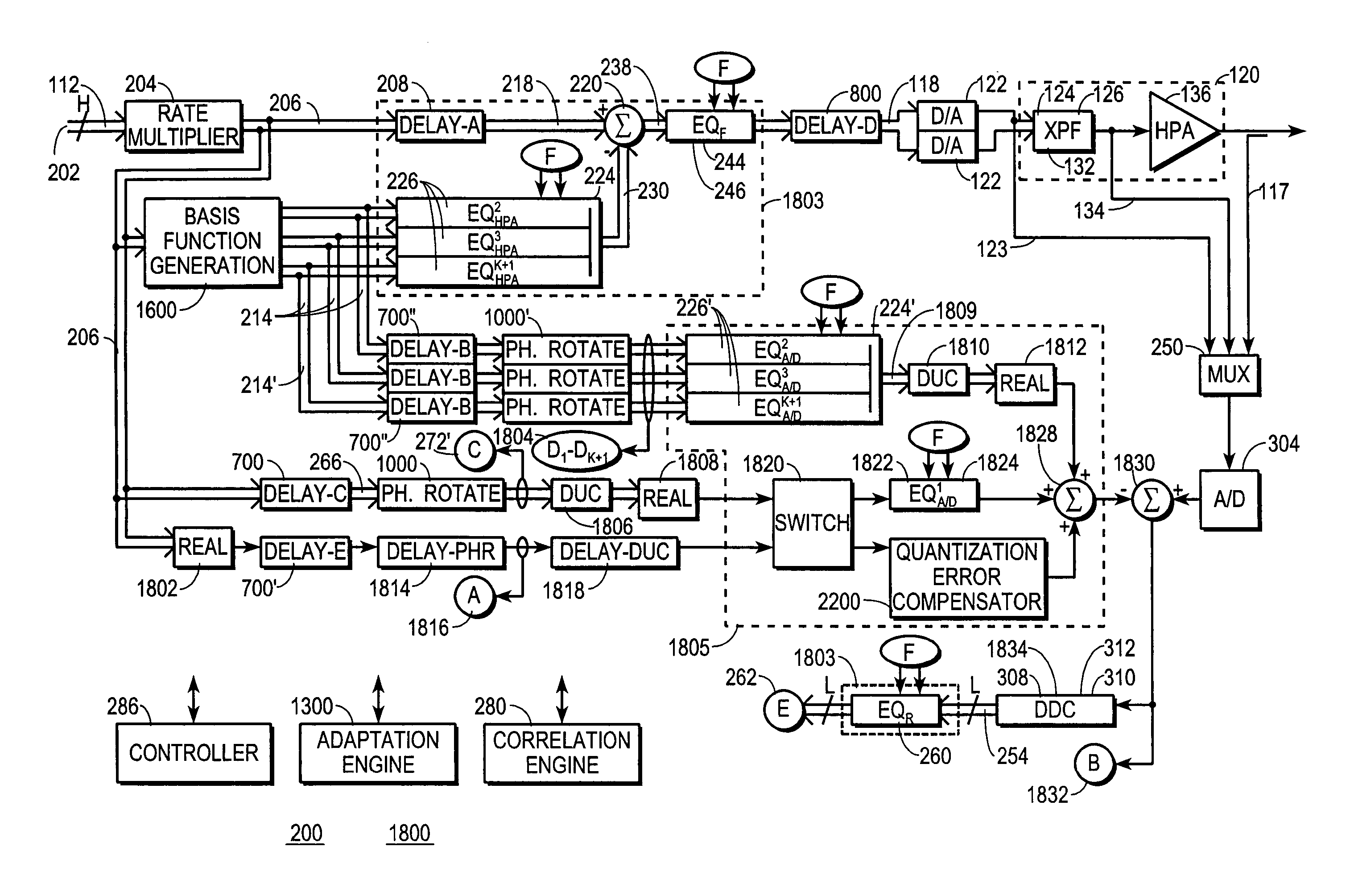
[0225]FIG. 18 shows a block diagram of the linear-and-nonlinear-predistortion section 200, referred to below as predistortion circuit 1800, of transmitter 100. Predistortion circuit 1800 is configured to compensate for some A / D-introduced distortions in addition to the linear and nonlinear distortions discussed above in connection with FIGS. 2-17. Through the use of predistortion circuit 1800, transmitter 100 may even use an inexpensive A / D that introduces significant amounts of distortion into the feedback signals it processes.
[0226]Predistortion circuit 1800 is configured much like predistortion circuit 200, and the above-presented discussion concerning predistortion circuit 200 for the most part applies to predistortion circuit 1800. Like reference numbers refer to similar components between the block diagrams of FIGS. 1, 2 and 18. However, for convenience certain segments of predistortion circuit 200, such as gain adjustment circuits 302 and 256, heat-change estimation circuit 1...
first embodiment
[0244]Predistortion circuit 1800 compensates for A / D quantization error, but more particularly dissymmetry, using quantization-error compensator 2200. FIG. 22 shows a block diagram of a representative quantization-error compensator 2200. In general, quantization-error compensator 2200 allows the formation of effective switching thresholds 2108′ that are ideally positioned, at least to within the precision of D / A 122. Another embodiment for quantization-error compensator 2200 is discussed below in connection with FIG. 31.
[0245]Referring to FIG. 22, a positive offset is added at a combining circuit 2202 to the analog feedback input signal driving A / D 304. The positive offset is not a requirement but is used here merely to simplify the hardware. Desirably, the positive offset is slightly greater than the maximum amount by which an actual switching threshold 2108 may be displaced in a negative direction from an ideal switching threshold. Thus, the positive offset has the effect of shift...
third embodiment
[0282]FIG. 28 shows a block diagram of the linear-and-nonlinear-predistortion section 200, referred to below as predistortion circuit 2800, of transmitter 100. Predistortion circuit 2800 is configured to perform predistortion and other transmitter processing in a way that meets error-vector magnitude (EVM) and / or signal-to-noise (S / N) requirements for both weaker and stronger channels transmitted from transmitter 100.
[0283]Predistortion circuit 2800 is configured much like predistortion circuits 200 and 1800, and the above-presented discussion concerning predistortion circuits 200 and 1800 for the most part applies to predistortion circuit 2800. Like reference numbers refer to similar components between the block diagrams of FIGS. 1, 2, 18 and 28. However, for convenience certain segments of predistortion circuits 200 and 1800, such as gain adjustment circuits 302 and 256, heat-change estimation circuit 1700, and circuits for generating clock signals for A / D 304, rate multiplier 204...
PUM
 Abstract
Description
Claims
Application Information