Impedance based devices and methods for use in assays

a technology of impedance and assay, applied in the direction of liquid/fluent solid measurement, electrochemical variables of materials, instruments, etc., can solve the problems of less than optimal efficiency, less than optimal sensitivity of such devices, and complicated impedance sensors with two layered structures, etc., to reduce gap size, increase cell number index, and increase the magnitude of impedance change

Active Publication Date: 2008-12-30
AGILENT TECH INC
View PDF81 Cites 145 Cited by
  • Summary
  • Abstract
  • Description
  • Claims
  • Application Information

AI Technical Summary

Benefits of technology

[0025]Toward measurement of the impedance changes associated with these events, methods are provided for the use of the device. One embodiment of the device utilizes a microtiter plate-like design which is especially well adapted to use with automated assaying equipment. The device according to this embodiment of the invention takes the form of a nonconductive substrate plate, onto which one or more containers to serve as cell or small molecule sample receptacles are placed, preferably in perpendicular relationship to the substrate. Electrical conduits are provided within one or more planes of the substrate, to connect its active sensors to an impedance signal processor. The conduits are configured to minimize background noise and the potential for conduit-to-conduit interference.

Problems solved by technology

However, this impedance sensor with two layered structures is somewhat complicated with the measuring electrodes on one layer and the reference electrodes on another layer.
However, this impedance sensor can monitor responses of only single cells.
Furthermore, the sensitivity of such devices critically depends on the cell location relative to the electrodes.
These methods use expensive substrates such as silicon and sapphire and, due to the electrode configurations (both electrode widths and gaps are about 50 microns), have a less than optimal efficiency, as only an average of about 50% of the cells are able to contribute to the impedance signal.
However, these electrodes are not optimized for a quantitative measurement of impedance at the interface between a cell and a microelectrode.
Despite its success of the coulter principle, the device is limited in its sensitivity as well as its dynamic range in counting and sizing biological cells.
However, these devices are limited to use in specific applications, and are not intended for general laboratory research.
However, the usefulness of the Cramer device is limited by several design limitations including, in one embodiment, the concealment of the active surface of the sensor by the membrane.

Method used


Image

  • Impedance based devices and methods for use in assays
  • Impedance based devices and methods for use in assays
  • Impedance based devices and methods for use in assays

Examples


example 1

Resistance and Capacitive Reactance for 8 Different Types of Electrodes Attached with or without Cells

[0370]FIG. 26 illustrates resistance and reactance for 8 different types of electrodes attached with or without NIH 3T3 cells. The unit for both resistance and reactance is Ohm. The magnitudes of the reactance were plotted in a log-scale. Note that the polarity for the reactance at most of the frequencies was negative (capacitive reactance). The diameter of the electrode for 2AA, 2AB, 2AC, 2AD, and 3A is 1 mm; the diameter of the electrode for 2BE, 3B and 3C is 3 mm. The features of each electrode types are different and are summarized in Table 1. The surfaces of electrodes were coated with chemical and biological molecules. In this experiment, fibronectin was used. After coating, NIH 3T3 cells were then seeded onto the surfaces of the electrodes. The resistance and reactance (capacitive reactance) were measured at 0 hour (immediately after seeding the cells) and at two hours after ...

example 2

Quantitative Measurement of Cells Using the 3B Electrode

[0372]FIG. 27 illustrates quantitative measurement of cells using the electrodes of 3B geometry. The apparatuses for experiments were constructed by gluing bottom less, conical or cylinder shaped plastic tubes over glass substrates on which 3B electrodes were fabricated. The plastic tubes had a diameter of about 5.5 mm on the end that was glued onto the glass substrates. The glass substrates formed the bottom of the wells (or fluidic containers) and the plastic tubes form the wall of the wells (or fluidic containers). Serial diluted NIH 3T3 cells (10,000 cells, 5,000 cells, 2,500 cells, 1,250 cells and 625 cells) were added into the apparatuses and onto the surface of the 3B electrodes that had been coated with fibronectin. Resistance and reactance were measured at 0 hour (immediately after seeding), and at 16 hours after seeding. The curves represent resistance and capacitive reactance data from a given frequency as indicated....

example 3

Real Time Monitoring of NIH 3T3 and PAE Cell Proliferation Using the 3C and 3B Electrodes

[0373]FIG. 28 illustrates real time monitoring of NIH 3T3 and porcine aortic endothelia (PAE) cell proliferation using the 3C and 3B electrodes. The apparatuses for experiments were constructed using similar methods to those described for FIG. 26 and FIG. 27. Two thousand five hundred NIH 3T3 cells and 2,500 PAE cells were seeded onto the coated electrodes. For NIH 3T3 cells, the electrode was coated with fibronectin; for PAE cells, the electrode was coated with gelatin. Resistance and capacitive reactance were measured daily to monitor the cell proliferation. Note that the polarity for the reactance at the frequency of 792 kHz was negative (capacitive reactance) and the magnitudes of the reactance were shown. Day 0 indicates the measurement immediately after seeding of the cells. Here, the capacitive reactance value shown in the figure is the absolute value. The resistance and capacitive reacta...


PUM

PropertyMeasurementUnit
widthaaaaaaaaaa
widthsaaaaaaaaaa
widthsaaaaaaaaaa

Abstract

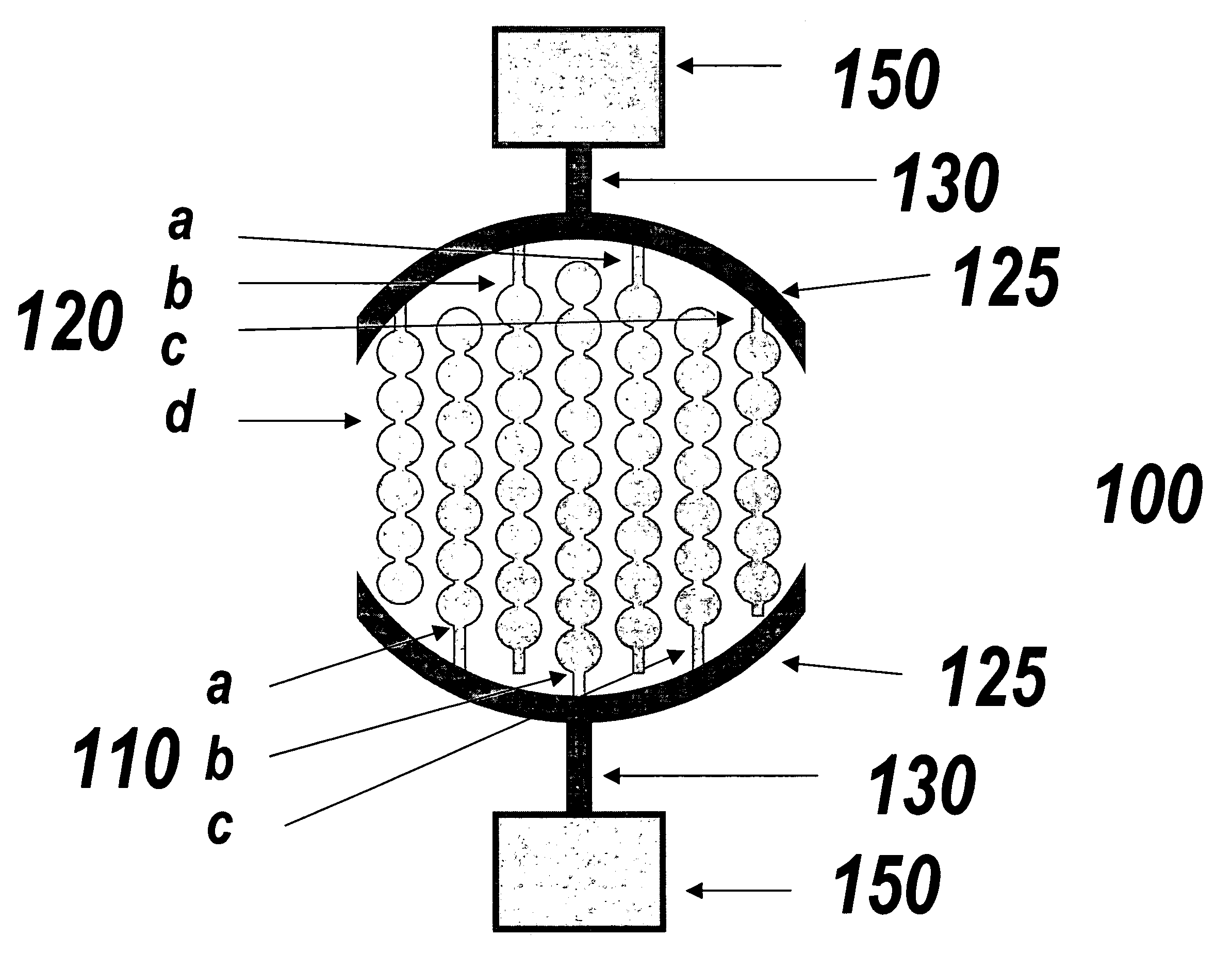
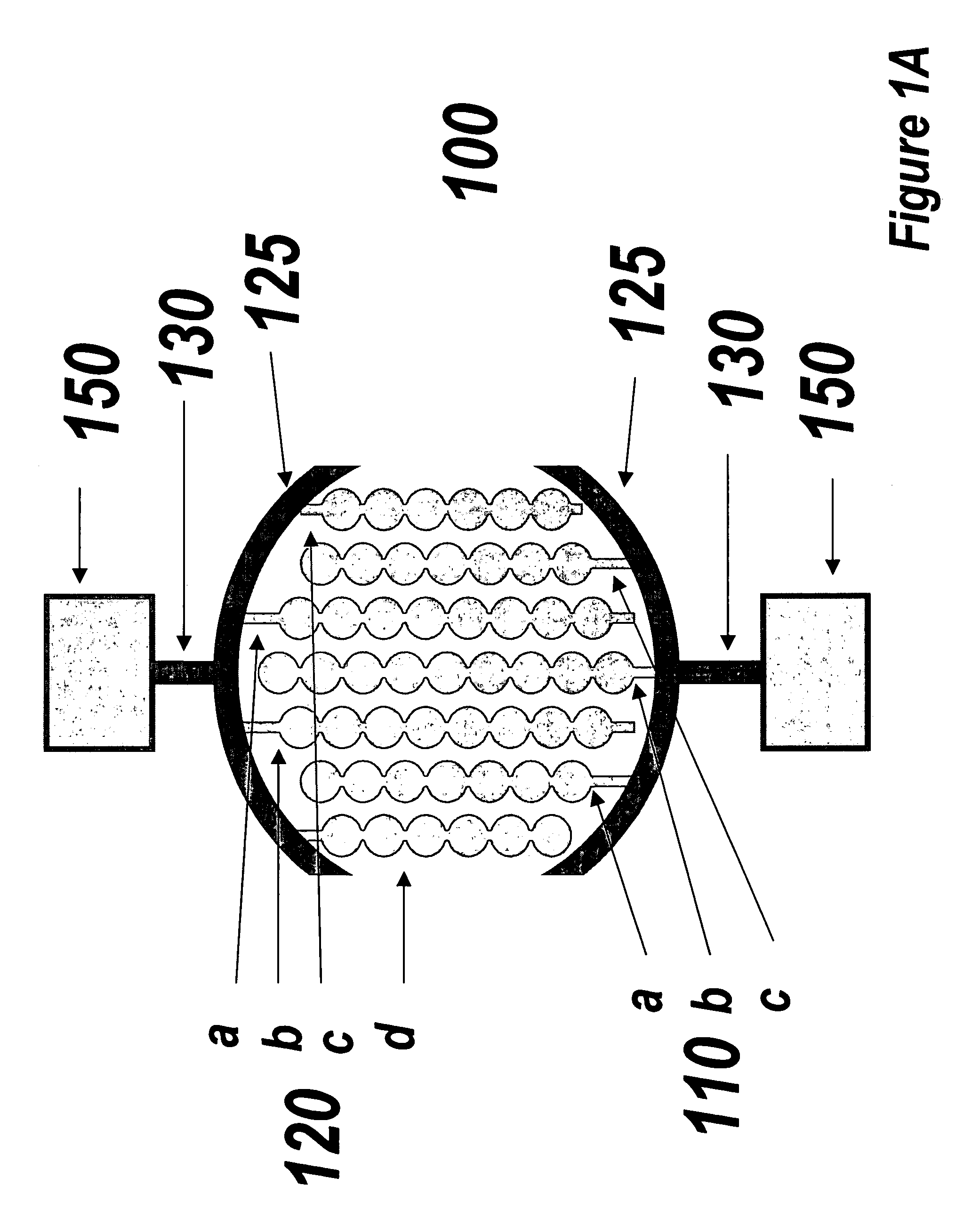
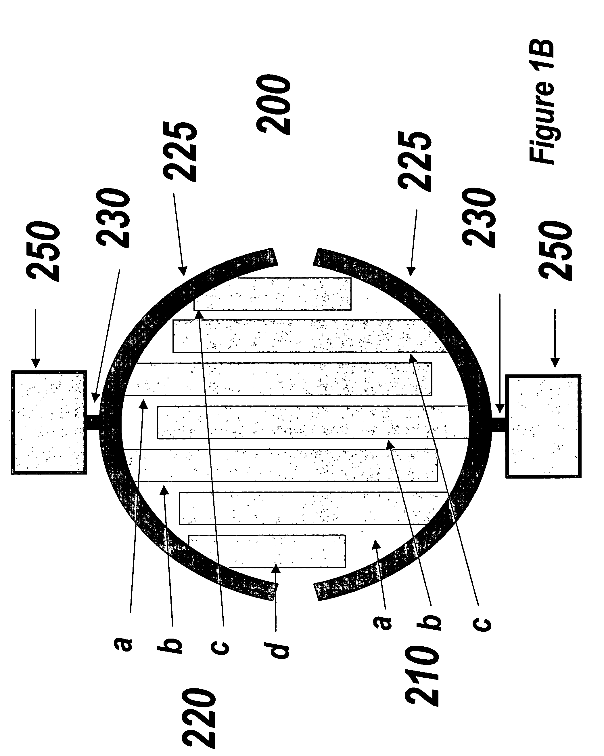
A device for detecting cells and / or molecules on an electrode surface is disclosed. The device detects cells and / or molecules through measurement of impedence changes resulting from the cells and / or molecules. A disclosed embodiment of the device includes a substrate having two opposing ends along a longitudinal axis. A plurality of electrode arrays are positioned on the substrate. Each electrode array includes at least two electrodes, and each electrode is separated from at least one adjacent electrode in the electrode array by an expanse of non-conductive material. The electrode has a width at its widest point of more than about 1.5 and less than about 10 times the width of the expanse of non-conductive material. The device also includes electrically conductive traces extending substantially longitudinally to one of the two opposing ends of the substrate without intersecting another trace. Each trace is in electrical communication with at least one of the electrode arrays.

Description

[0001]This application claims benefit of priority to U.S. provisional application No. 60 / 397,749, filed on Jul. 20, 2002; U.S. provisional application No. 60 / 435,400, filed on Dec. 20, 2002; and U.S. Provisional application 60 / 469,572, filed on May 9, 2003, each of which is incorporated by reference herein, and claims benefit of priority to PCT Application No. PCT / US03 / 22557; entitled “IMPEDANCE BASED DEVICES AND METHODS FOR USE IN ASSAYS,” filed Jul. 18, 2003, which is incorporated by reference herein. This application also incorporates by reference PCT Application No. PCT / US03 / 22537, entitled “IMPEDANCE BASED APPARATUSES AND METHODS FOR ANALYZING CELLS AND PARTICLES”, filed Jul. 18, 2003.BACKGROUND OF THE INVENTION[0002]1. Technical Field[0003]This invention relates generally to the field of sensors for use in cell and molecule based assays. In particular, the invention provides sensor devices which detect a change in measured impedance between and among electrodes, from which the...

Claims


Application Information

Patent Timeline
Patent Type & Authority Patents(United States)
IPC IPC(8): C12M1/42C12M1/34C12M3/00C12M1/36C12M1/38C12Q1/00
CPCC12M23/12C12M41/36G01N27/3276G01N27/02Y10T29/49117
Inventor XU, XIAOWANG, XIAOBO
Owner AGILENT TECH INC
Why Eureka
Try Eureka