Lapping machine and head device manufacturing method

a manufacturing method and technology of a head device, which are applied in the direction of lapping machines, manufacturing tools, instruments, etc., can solve the problems of maximizing existing space and difficulty in maintaining the coplanarity of the bottom surfaces of both blocks, and achieve the effect of easy manufacturing and excellent yield

Inactive Publication Date: 2009-01-06
FUJITSU LTD
View PDF9 Cites 0 Cited by
  • Summary
  • Abstract
  • Description
  • Claims
  • Application Information

AI Technical Summary

Benefits of technology

[0010]Accordingly, it is an exemplified object of the present invention to provide an easily manufactured lapping machine with an excellent yield, and a head device manufacturing method.
[0011]A lapping machine according to one aspect of the present invention that polishes a head block in which plural head devices are connected in a row includes a jig that has a bottom surface that opposes to a grinding plane, and fixes the head block onto the bottom surface, a pressure mechanism that applies a pressure to the head block against the grinding plane, a detector that is connected to the head block and detects a grinding amount of the head block, and a dummy block fixed onto the bottom surface adjacent to the head block. This jig (transfer tool) has the dummy block adjacent to the head block on the bottom surface of the jig, because it is difficult to provide the dummy block on the side surface as in JP 2005-131727 when the pressure mechanism and the printed board are arranged at both sides of the jig. The dummy block blocks diamonds and lap dusts that exist on the lapping board or grinding plane and prevents damages of the TuMR device in the head block by providing the dummy block on the upstream side and reducing a distance between the dummy block and the head block. Therefore, the yield improves even without expensive fine diamonds. The inventive lapping machine fixes both blocks on the bottom surface of the same component, i.e., the jig. When these blocks are attached to separate members as in JP 2005-131727, it is difficult to maintain the coplanarity of the bottom surfaces of both blocks on the grinding plane side due to processing errors of the separate members and the attachment errors of both blocks. The inventive lapping machine thus facilitates maintenance of the coplanarity of the bottom surfaces of both blocks on the grinding plane side. The inventive lapping machine does not require the keeper 26 or the jig 24 unlike JP 2005-131727, and can maintain the miniaturization of the lapping machine.
[0012]Preferably, a surface of the head block on a side of the grinding plane and a surface of the dummy block on the side of the grinding plane are parallel to the grinding plane and coplanar. Preferably, a width of the dummy block is constant, and a total of the width is more than twice as long as the head block. For plural dummy blocks, the “total of the width” means a total of the widths of the dummy blocks. For one dummy block, the “total of the width” means one width. This configuration can provide high-quality polishing of the head block.
[0013]The jig may have first and second side surfaces perpendicular to the bottom surface, and a perforation hole that perforates through the first and second side surfaces, and the pressure mechanism may use a linkage that partially protrudes in the perforation hole in the jig. When the pressure mechanism uses the linkage as in JP 2005-007571, the jig is thicker than the head block. It is therefore unnecessary to provide a mounting space of the dummy block on the bottom surface of the jig or to thicken the jig, maximizing the existing space.
[0015]A head device manufacturing method according to another aspect of the present invention by polishing a head block in which plural head devices are connected in row includes the steps of fixing a head block onto a bottom surface of a jig that has the bottom surface opposing to a grinding plane, and fixing a dummy block onto the bottom surface adjacent to the head block. This manufacturing method can manufacture the above head device more easily. The present invention is particularly suitable when it is difficult to provide the dummy block on any one of the side surfaces. The dummy block is preferably arranged on an upstream side of grinding. The dummy block blocks diamonds and lap dusts that exist on the lapping board or grinding plane and prevents damages of the TuMR device in the head block by providing the dummy block on the upstream side and reducing a distance between the dummy block and the head block. Therefore, the yield improves even without expensive fine diamonds.

Problems solved by technology

When these blocks are attached to separate members as in JP 2005-131727, it is difficult to maintain the coplanarity of the bottom surfaces of both blocks on the grinding plane side due to processing errors of the separate members and the attachment errors of both blocks.
It is therefore unnecessary to provide a mounting space of the dummy block on the bottom surface of the jig or to thicken the jig, maximizing the existing space.

Method used


Image

  • Lapping machine and head device manufacturing method
  • Lapping machine and head device manufacturing method
  • Lapping machine and head device manufacturing method

Examples


Embodiment Construction

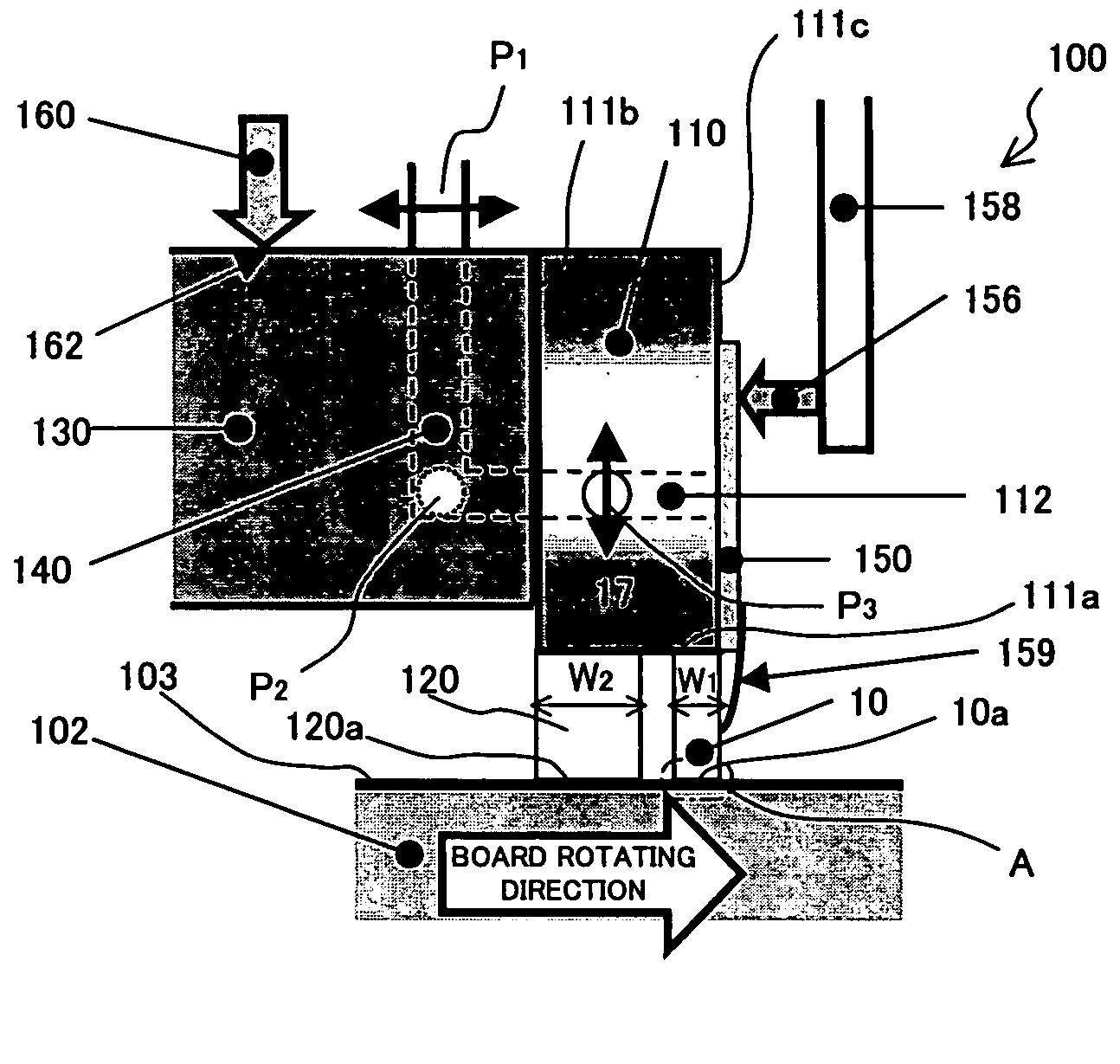
[0033]Referring now to the accompanying drawings, a description will be given of a lapping machine 100 according to one embodiment of the present invention. Here, FIG. 1 is a schematic partial section of principal part of the lapping machine 100 according to this embodiment. The lapping machine 100 includes a lapping board 102, a transfer tool (jig) 110, a dummy block 120, a machine head 130, a link pressure mechanism 140, a printed board 150, and a follow-up mechanism 160.

[0034]The lapping board 102 rotates in an arrow direction, and has a grinding plane 103. Slurry that contains diamonds is supplied to the grinding plane 103 from the left side in FIG. 1. This embodiment does not require expensive fine diamonds, as described later.

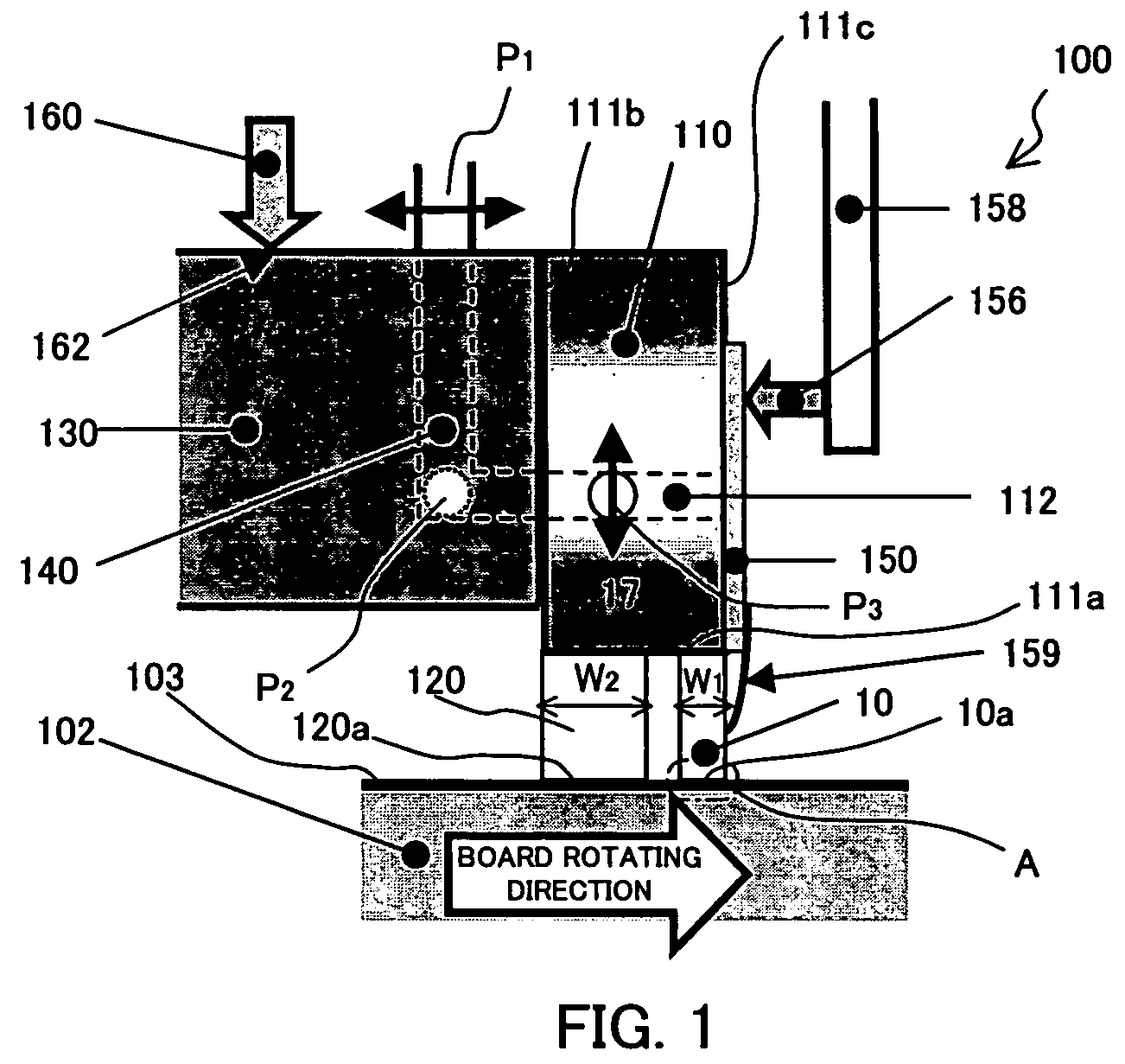
[0035]The transfer tool 110 has a plate shape when laterally viewed as shown in FIG. 1, and has a convex shape when viewed from the front as shown in FIG. 2. Here, FIG. 2 is a photograph of the front of the transfer tool 110.

[0036]The transfer tool 110 ha...


PUM

PropertyMeasurementUnit
pressureaaaaaaaaaa
structureaaaaaaaaaa
widthaaaaaaaaaa

Abstract

A lapping machine that polishes a head block in which plural head devices are connected in a row includes a jig that has a bottom surface that opposes to a grinding plane, and fixes the head block onto the bottom surface, a pressure mechanism that applies a pressure to the head block against the grinding plane, a detector that is connected to the head block and detects a grinding amount of the head block, and a dummy block fixed onto the bottom surface adjacent to the head block.

Description

[0001]This application claims the right of a foreign priority based on Japanese Patent Application No. 2006-205654, filed on Jul. 28, 2006, which is hereby incorporated by reference herein in its entirety as if fully set forth herein.BACKGROUND OF THE INVENTION[0002]The present invention relates generally to a lapping or grinder machine and a head device manufacturing method, and more particularly to a lapping machine that equalizes the height of a head block (also referred to as a “row bar”) in which plural head devices are connected in row, and a method that grinds or polishes the head block and manufactures the head device. The present invention is suitable, for example, for a lapping machine for a head device in a hard disc drive (“HDD”).[0003]Along with the recent spread of the Internet etc., inexpensive hard disc drives that can record a large amount of information including images have been increasingly demanded. When the surface recording density is increased to meet the dem...

Claims


Application Information

Patent Timeline
Patent Type & Authority Patents(United States)
IPC IPC(8): B24B49/00B24B37/005B24B37/04B24B37/30B24B49/04
CPCB24B37/042Y10T29/49037
Inventor NAKAJIMA, KIYOTAKA
Owner FUJITSU LTD
Why Eureka
Try Eureka